Shop improves manufacturing with simulation software
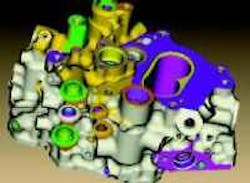
Using Vericut CNC simulation software, Tell Tool reduces manual-prove-out-process time by as much as 80% for such parts as this jet-engine, fuel-metering unit that combines fuel pump and carburetor in one.
Tell Tool of Westfield, Mass., has integrated Vericut CNC simulation software into its NC-program prove-out process. It ensures every part is accurate, dimensionally correct, and efficient when they hit the shop floor. As a result, the company reduces manual prove-out processes by as much as 80% and practices lights-out machining on some of its first-time parts to improve efficiency, productivity, and profitability.
Besides electronic engine controls, auxiliary power units, and other systems, Tell Tool manufactures fuel-control units using Vericut's model export capability integrated into the manufacturing process. When customers contract Tell Tool for a fuel-control unit, there is often no design model of the final part shape. What Tell Tool gets are specifications for the dimensions of the inside of the part, minimum wall thicknesses, specific structure requirements, and other information.
To create the outer shape of the control unit, Tell Tool reverse engineers the unit from the inside out using internal-part specifications such as fuel-control-housing dimensions and the minimum wrap-stock requirements around each feature. Within a CAD/CAM system, it creates cutter paths around the minimum wrap-stock requirements, which run in Vericut to create the in-process part shape.
Vericut exports the in-process shape as an in-process file that converts to an STL file, which serves as a starting point for programming the next operation in the CAD/CAM system. After the part is programmed and run through Vericut, there is an in-process model of the fuel-control housing's shape. This finished shape, which can convert to an STL file, goes back to the customer.
Prior to implementing Vericut, programmers approximated as to the shape of the in-process material and ran the cutter path within those imaginary boundaries. As a result, there were a lot of air cuts where the cutter did not contact material.
For companies like Tell Tool, the latest release of Vericut, version 5.4, also improves documentation processes. Such software contains the critical manufacturing information, especially a representation of the in-process geometry, necessary to accurately document a process. One example is creating inspection instructions. Vericut 5.4 automatically creates inspection instructions complete with in-process feature dimensions, which are generated during NC-program simulation. Most shops manually create inspection instructions. However, without an electronic in-process model of the part, there is a limited knowledge of the in-process state of material. Thus, manual methods require a certain degree of technical expertise and are prone to error.
CG Tech
Irvine, Calif.
cgtech.com
