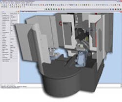
CGTech Releases Verticut 6.1 Machine Simulation and Optimization Software
The new version has NC Program Review integrated into Vericut’s main desktop, improved CAD/CAM interfaces that enable verifying NC programs from within CAD/ CAM software, improved controls over machine configurations, and turning tools with multiple inserts are now supported.
According to CGTech, when in Review mode, the user can navigate backwards from the last NC program line simulated.
Error messages and NC program text are highlighted when a collision on the workpiece or fixture is selected. Entering Review mode adds Step Backward and Play Backward buttons to Vericut’s other VCR buttons.
The existing Step, Play, Rewind and Reset buttons also change to interact in Review mode, providing easy navigation through the NC program.
Optionally, material can be replaced while stepping backwards, then removed again while stepping forward, giving the ability to easily identify and closely evaluate problem areas.
Both machine views and profile views now are active in Review mode, including an optional tool path line display in the profile view. Additionally, synchronized subsystem simulation (such as for multi-channel controls) can now be displayed in Review mode.
CGTech says its CAD/CAM interfaces updates make verifying NC Programs from within the CAD/CAM system easy and convenient.
Users can verify individual operations, a series of operations, or a set of complete NC programs. All stock, fixture, and design geometry is transferred automatically to Vericut in the correct orientation, along with the NC program, tooling, machine and control data and other simulation parameters. Vericut simulates the post-processed CNC code output from the CAM system and therefore complements the toolpath simulation provided by many CAM systems.
The following CAD/CAM interface updates have been made in 6.1:
- Unigraphics Interface — merges tools from the UG session with tools in the template project file’s Tool Library.
- CATV Interface — CATIA V5 users can choose how to apply the part operation’s machining axis in their Vericut simulation by selecting the offset table (Program Zero, Work Offset, etc.) and relationship to the machine (tool, rotary axis pivot, etc.). CATV allows the user to select sketch geometry used to define tool shapes in CATIA. This geometry is then used to create tools in Vericut.
- Interfaces to Delcam PowerMill, Open Mind HyperMill and Gibbs CAM are also available.
Turning tools with multiple inserts (such as “Flash” tools or other types of tools with multiple inserts) now are supported —including definition of multiple driven points.
Each insert’s position is checked for valid turning orientation before it will cut. Cutting limit checking (added in 6.0) is enhanced to include checking Minimum/ Maximum RPM values. A new model choice automatically creates a milling tool’s gage location at the highest point on the tool assembly.
