No Nonsense, Non-Round Part Grinding
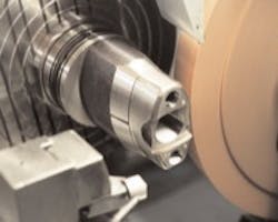
A cylindrical grinder could do all these non-round features in one setup, said Cinetic Landis Grinding.
CYLINDRICAL GRINDERS are improving productivity in machining non-round part shapes. Shops that do non-round grinding have used cam-actuated grinders or a combination of surface and tool grinders in the past, and those processes have proved inflexible in production and cumbersome to set up.
On the other hand, cylindrical grinders deliver flexibility in the types of grinding jobs they can handle, while maintaining the accuracy and rigidity that shops need to reduce production costs. In addition, cylindrical grinders let shops do more part operations with fewer machine setups.
Successful non-round grinding on a cylindrical grinder depends on accurate machine movement because the process is an interpolation of two machine axes — the C axis, which is the workpiece rotation, and the X axis, which is the wheelhead. The grinding wheelhead feeds in and out from the workpiece and follows the contour of non-round part profiles. It constantly reverses directions in the X axis while, simultaneously, the workhead spindle speeds up and slows down the workpiece rotation to maintain the consistent load on the grinding wheel and prevent part surface flaws.
To ensure accurate axis movement, many cylindrical grinding machine builders incorporate hydrostatic ways, linear motors, and high-resolution scales on the X axes along with integral-motor-type, direct-drive hydrostatic spindles and rotary encoders for the C axes. All of these components work together to nearly eliminate backlash and stick-slip for both the X and the C axes.
"What shops have to be most concerned about in non-round grinding is a ‘jerking' motion when a machine's axis reverses directions," said Dwight Myers, manager of bid and proposal at Cinetic Landis Grinding Corp. (www.cinetic-industries.com/landisus). "A machine with ballscrews, for example, experiences compliance (jerking and/or deflection) when the axis reverses direction. On the other hand, linear motors and hydrostatic way systems provide the necessary stiffness to eliminate such an occurrence."
According to Nelson Beaulieu, grinding products manager for Kellenberger grinders at Hardinge Inc. (www.hardinge.com), hydrostatic ways permit grinders to make extremely slow moves without stick-slip that can cause imperceptible axisreversal marks on part surfaces and profiles. Beaulieu also points out that hydrostatic spindles eliminate spindlereversing errors that could be recognizable on part surfaces and errors from the fluctuations of the grinding load when grinding occurs above or below centerline, which is often the case in non-round part grinding. Hydrostatic spindles remain rigid even though the load on them may vary, he added.
In addition to hydrostatic bearings, most builders use integral direct-drive spindles for the C axes on cylindrical grinders that are intended for nonround part grinding. Such spindles are directly coupled to the servo motors that drive them. These motors are actually built into the rotary axis itself, and eliminate the need for belts or gearing that Eugene Supernor said would compromise axis accuracy. Supernor is president of the spindle division at Bryant Grinder Corp., a division of Vermont Machine Tool (www.vermontmachinetool.com).
Not all builders use hydrodynamic spindles. Studer equips its cylindrical grinders with direct-drive spindles that use high-precision ball-bearings instead. Hans Ueltschi, national sales manager for the Studer cylindrical division of United Grinding Technologies Inc. (www.grinding.com), said the company has found that the ballbearing spindles provide increased rigidity in variable-speed situations and react better to changing process conditions for non-round parts.
While hydrostatic ways, linear motors and direct-drive spindles provide accurate motion, it takes special software working with a capable CNC to program and synchronize their movements. Attempting to grind non-round parts on a cylindrical grinder without such software would require manually programming the changes in workpiece speed and wheel feed.
In non-round part grinding, workpiece speeds and grinding wheel feeds must change constantly to cope with varying metal-removal rates. For example, a shop may run three or four different workpiece-rotation speeds through one revolution of a nonround part form, and the software must initiate those changes in workpiece speed or wheel feed.
Special software packages also allow shops to apply high-speed machining techniques to non-round grinding to further optimize the process. Essentially, the high-speed machining techniques used in grinding rely on changes in workpiece-rotation speeds to maintain constant grinding surface footage. If workpiece rpm remains constant during non-round grinding, some parts of the workpiece would turn too slow, while others would turn too fast. Areas that are turned too slow exhibit concaves and burns because the wheel dwells on them for too long. Conversely, areas turned too fast are not cut correctly, so deviations can form.
"Think of the grinding wheel as a cutting tool," explained Ueltschi. When milling a part, shops do not run the cutter at a constant feedrate. They speed it up on straight passes and slow it down in corners to maintain a steady chip load on the tool. The same is true for high-speed, non-round grinding.
In addition to the challenge of maintaining a steady chip load, shops that do non-round grinding must generate smooth transitions and tangents from one part feature to the next. For example, the proper radius is needed between a curve and a flat in a part to blend the two features, such as those found on punches.
Lags in machine movement, problems with tooling or setup, software reaction time, and how a machine was programmed all can cause poor tangents and blending between part features. But more often than not poor quality in grinding non-round parts is due to the lack of rigidity. That is why nearly every cylindrical grinding machine builder agrees that accurate non-round grinding operations must start with a rigid machine platform that includes heavy-duty components mounted to thermally and mechanically stable bases.
Photo courtesy of Kellenberger
