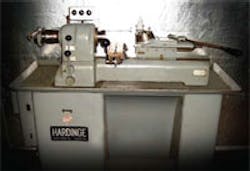
Teach an Old Lathe New Tricks
These little machines, commonly referred to as “second operation lathes,” are astoundingly productive pieces of equipment that still have great value in almost any machine shop, even in the face of the CNC tidal wave that seems to be overwhelming the machine industry.
These used Hardinge turret lathes are inexpensive, readily available and use commonly available tooling. Once set up, a minimally trained operator can man the machine and generate production that will rival most CNC machines. These attributes allow the lathes to produce substantial quantities of high-precision parts at very low costs per unit.
Unfortunately, these old lathes have one slight flaw, their spindle-speedcontrol systems. Most machinists who have used the machines would agree that the speed-control system is ok, but a more flexible system would be a great improvement.
Generally, the spindle motors of these lathes are two-speed, 3-phase types with 1,750 and 825-rpm ranges. Motor speed and direction are easily changed during operation via a pair of levers mounted on the front of the spindle, which actuate large drum switches mounted in the control cabinet.
Drive systems come in two different varieties, fixed-belt and a vary-drive. The fixed-belt system uses a step pulley arrangement to change spindle speeds, which provides the machinist with only two easily changeable speeds during operation. The vary-drive uses a pair of variable sheaves controlled with a set of buttons adjacent to a speed indicator mounted on the top of the spindle.
The vary-drive retains the twospeed motor and is a significant improvement over the fixed system. However, the vary-drive is slow to change and has a tendency to disrupt the flow of production. In addition, the two-speed motor selection will only allow the machinist to halve the spindle speed at any given setting, which can hinder production.
This is why I configured a system that would retain the factory lever controls but expand on their basic function.
Coupled with GS-2 variablefrequency drives from Automation Direct (www.automationdirect.com), my arrangement provides the machinist quick access to a wide range of speed variations.
How it’s done
The original lathe controls consisted of a fairly traditional motor controller with two heater blocks, a control transformer and a collection of lesser components, including a front-mounted panel switch rated at 2 hp. A pair of drum switches mounted on the back plane of the control cabinet controls the forward and reverse functions.
Even though they are a bit over-kill for logic switching, I retained these original drum switches because they were extremely high-quality units and provided excellent tactile feedback to the operator.
For this particular project, I first designed a wiring schematic that shows how simple a wiring system can be when using a GS-2 variable-frequency drive.
In the schematic (opposite page), M1 is the spindle motor, M2 is the coolant pump, S1 is the original panel toggle switch, S3 is the speed control drum switch and S2 is the forward/off/reverse drum switch. I specified fuses for the main line and the coolant pump.
The metal oxide veristor (MOV) suppresses inductive kick back when the coolant motor is turned off. R1 is a 200-ohm, 100-W braking resistor for electrical braking action.
This feature of the GS-2 allows for completely removing the old mechanical brake that was originally supplied from the factory.
P1 through P3 are 5-K-ohm potentiometers that provide quick adjustment to each of the three speeds selected by the lever on the front of the spindle. Since the potentiometers are mounted on the top of the spindle, a shielded cable is specified per the drive manual’s recommendation.
As a second step, I configured a small cabinet for carrying the three potentiometers wired to a shielded cable. I also designed a simple pin bracket, so it could be mounted into one of the existing equipment holes on the back of the spindle head.
Next, I designed the control system to fit with the existing machine configuration, to produce a general layout that guides the technician in the placement of the major components and routing of cables.
Within the control cabinet, the GS-2 is mounted at the upper left of the panel, and the braking resistors are placed just below it.
The original toggle switch now is used as the primary power and connects to a double fuse block. A single-pole toggle switch was installed in the hole left by the original push button actuator. This switch overrides the coolant pump, which plugs into a 120-V receptacle.
After familiarizing myself with the GS-2 drive, I found that setting the parameters was a rather simple, stepby- step, process. I double checked all of the completed wiring, turned on the power to the GS-2 and set up the basic parameters for the selected motor.
I then programmed the source of frequency control to accept input from the potentiometers and set the acceleration and deceleration time to one second.
There was a slight amount of over-spin (continued rotation) after the spindle was turned off, so I adjusted the DC injection current level, DC injection during stopping and the start-point for DC injection. That stopped the spindle dead when the switch was turned off.
Overall material costs for the project were $461.97.
This is a small cost to bear, considering that the project reduced our manufacturing time for two of our parts by 60 percent and for three others by approximately 35 percent. That translated to the total material costs of the projects being paid off in one production run.
By Brian Elliott Chief of Engineering and Manufacturing at Air Options Inc. ([email protected])
