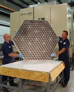
New space telescope relies on precision machining of its mirror
FRANKLIN LAKES, NJ — John Mather, winner of the 2006 Nobel Prize in Physics and project scientist for the James Webb Space Telescope, is one of many overseeing the project at NASA's Goddard Space Flight Center. The James Webb Space Telescope is scheduled for launch in June 2013. James Webb Space Telescope is designed to study the earliest galaxies and some of the first stars formed after the Big Bang. One of the most important components of the James Webb Space Telescope is its 6.5 meter mirror that is comprised of 18 beryllium segments. The mirror is the largest lightweight beryllium optic that has ever been made. Its segments were completed in March, 2007 by Axsys Technologies Inc. at its climate-controlled factory in Cullman, Alabama. Northrop Grumman Corp. is the prime contractor for James Webb Space Telescope. Each mirror segment is about 1.5 meters across. Axsys used eight Mitsui Seiki USA Inc. ( www.mitsuiseiki.com) machining centers to produce the segments. Mitsui Seiki supplied custom-built horizontal machining centers to produce the James Webb Space Telescope mirror segments. The machining centers combine a massive structure — the column weighs 11 tons, the bed is 20 tons — with the ability to position to within a few microns anywhere in the machining envelope. "These are very large, heavy machines; the components are substantial," says Scott Walker, president, Mitsui Seiki USA Inc. "However, they are also elegant in that they have to position and travel in a very specific, ultra precise manner." Machining begins when a 540 lb beryllium billet is fixtured vertically onto an angle plate on one of the eight Mitsui machines. The six-sided billet is 4 in. thick, 54 in. across, and 62 in. from point to point. The reverse side of each mirror segment has 600 pockets - about 2.5 in. square each. There are also 22 mounting pads and 249 light-weighting holes. Producing the pockets, pads and holes required about two months to complete. After pocket milling the reverse side, the billet weighed about 275 lbs. at this point. The segment was heat treated to relieve machining stresses, and then the mirror side was roughed before another stress-relief treatment. Roughing wass a circular cut that starts in the center, and worked its way out, and removing another 50 to 60 lbs. of material. The next operation was finish milling of the pocket side, which required another 10 weeks of machining time. "Consistent cutting is paramount in this application," said Walker. "Machining generates stress and a lot of material is being removed on these mirror segments. The cutting conditions, the toolpath, and how the servo motors control the toolpath to provide consistency of machine load are the keys to successful cutting of the mirror." After finish machining and chemical milling, the final dimensions on the pocket wall thicknesses range from 0.020 in. to .299". Finish milling of the mirror side, pocket side, and locator hubs was next. Tolerances for many of the finished elements of the mirror structure are +0.0002/-0.00", and true position is 0.001 in. from the inside to the outside of the hubs and 0.005 in. all the way around a 48 in. bolt circle. The mirror surface itself has a specified thickness of 0.098 in. with a profile tolerance of +/- .002 in.. The final machining operation was for 30, 0.250 in. diameter holes and slots on the edge and tolerances for those are +0.0002/-0.00". These holes are for tooling balls that are used to maintain a profile of the mirror surface during polishing. At Axsys, each segment required almost one year of processing that included machine time, heat treatment, and inspection. Parts were inspected at each step of the process for dimensional accuracy and for residual stresses. "Obviously the goal here was not speed, but accuracy," said Walker. "Contributing to machine precision is the foundation we recommended built under each machine. When Axsys designed the new building to house mirror production, they included a concrete pad under every machine at 39 in. thick. Each pad is surrounded by a bed of sand to isolate the machine from any vibration generated by neighboring equipment. Each machine is anchored to its pad using 27 anchor plates with four anchor bolts per plate for a total of 108 bolts."
