Practical Ideas: A Simplified Method for Producing Hob Teeth
Mark Grizotsky of Thornhill, Ontario, writes: My idea is to convert two radius-arc side profile teeth into two obtuse-angled sides that have the same pitch.
Hobs are for rough milling straight-side spline shafts on a gear-milling machine. The obtuse-angled sides are substituted for radius-profile sides, which are very complicated to calculate and produce. Our current research builds on a study of the milling process that shows that obtuse-angled profiles with teeth on two sides provide a very uniform grinding stock allowance, distributed very close to parallel to the spline sides.
This uniformity, of course, pays dividends in the efficiency and consistency of the final grinding process. The obtuse-angled sides of the hob teeth are inscribed in the arc-radius sides of the teeth. It appears as two obtuse-angled triangles that are inscribed in two radius sectors on both sides of the tooth.
The top of the obtuse angle is located in the middle of the arc radius (and half of the depth the tooth, H/2). H is the depth of the tooth from the pitch line to the horizontal edge of the tooth.
The triangle has three points: The first point, A, is the intersection of the pitch line with the bottom of the arc radius, or the width of the tooth, T. The second point, B, is located in the middle of the arc-radius, or the intersection of the horizontal line H/2. The third point, C, is the intersection of the top of the arc-radius with the top of the horizontal edge of the hob tooth.
But, to build the profile of the tooth and grinding abrasive wheel for the table method, we need a different design:
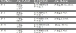
Across point A draw a vertical line and a small angle, M1. Then, draw point B on the arc-radius with coordinates X and Y. Ne x t, across B draw a vertical line and a larger angle, M2. M1 and X, Y, and M2 are given in the table below. H is the depth of the teeth. On points B and C we give a very small radius, 0.002 inch. Z is the number of splines of the shafts and obtuse angles that depend on Z and are independent from the outside diameters of the shafts (1 – 6 in.), according to our research. The angles and coordinates are calculated by computer program; H and T are calculated by standard formulas.
All degrees have tolerances of ±5 min.
Using this table we can easily design, build, and grind a profile of a hob tooth and counterplates for grinding and turning operations. A hob with two obtuse-angle sides is necessary also in case of emergency when we need to produce hobs in a very short period of time. As a precaution, I make a test cut before actually producing roughing straight-side spline shafts.
A diagram of the hub tooth.
About the Author
Mark Grizotsky
Owner
Mark Grizotsky, owner of MLG Tool Design in Willowdale, Ontario, has been a major contributor and influencer to machinists everywhere with his insights to machine design and set-up, tooling design and selection, and advice for preparation and processes.
