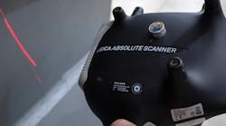
A combination of laser scales and thermal compensation systems is helping the aerospace industry improve accuracy when machining long, large parts.
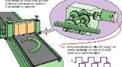
Rotary-encoder-equipped rack-and-pinion or ballscrew axis drives can only infer the position of machine components by monitoring the rotational position of the axis drive motor shaft. Laser scales, in contrast, measure actual physical distance of machine components. Both systems communicate with the CNC using two-channel A and B square wave quadrature signals for each axis.
Renishaw's new HS10 laser scale addresses two problems of machine inaccuracies: fluctuating environmental conditions and the inadequacies of traditional axis position measuring systems.
A laser scale uses interferometry to achieve extraordinary accuracy. Measurement units are wavelengths of light 0.633 µm long. A laser beam (1) starts as a circular, polarized beam of single-frequency light. A stationary beamsplitter/retroreflector splits the beam into horizontally and vertically polarized beams, and returns one, a "reference beam," (2) to the detectors.
The second beam (3) strikes a retroreflector attached to the moving part of the machine and is returned and recombined with the reference beam (4) before striking the detectors. In simple terms, the scale then counts the change in the number of wavelengths between the two beams, as the moving retroreflector travels. The feedback from the scale lets the CNC determine speed, direction, and distance.
The Macbormill, manufactured by Henri Liné of Granby, Quebec, Canada, is a CNC nine-axis gantry milling machine that produces precision parts. The thermal compensation system and laser scales integrated in the control of this and similar Henri Liné, long-travel, gantry mills work with the machine's rotary heads to significantly improve accuracy. Together, the two systems effectively reduce the impact of environmental fluctuations and eliminate errors introduced by conventional drives and less-precise precision feedback systems.
The device many machine tools use to measure their linear position is actually rotary in nature—an optical or magnetic encoder or resolver on the servomotor shaft, which drives the ballscrew. The machine CNC effectively "associates" a certain number of counts from this rotational device with linear positions for the spindle. If screw leads were true and drives backlash-free, this arrangement would be ideal. Unfortunately, these are inherent sources of linear error that machine tool makers compensate for with laser calibration and special software in the CNC. This is all well and good for axes of about a meter. Beyond that, it is a different story.
In the aerospace sector, machine tool axes are often longer than a meter, and glass scales, because of cost and physical limitations, are not a practical option for accuracy enhancement. Thus, the industry has been a driving force behind the development of a new laser-based linear position feedback system for large machines. It is complemented by a thermal compensation system that lets large aluminum parts be measured for temperature and machined accurately in a nontemperature-controlled environment.
This feedback system is yielding accuracy improvements up to 30 3 for large machine tools and assembly systems. Accuracy comes down to the repeatability of the machine—about one part per million on axes out to 250 ft, or about ±0.0004 in. for a 40-ft axis.
Because the feedback system measures the true position of a machine component, such as a column, it can be retrofitted to existing, older machines for positional accuracy improvement. Versions of this same technology are already in OEM use on new machines.
Addressing two sources of error
Machine inaccuracies tend to come from two sources. The first is the axis-position measuring system. Often, aerospace machines are equipped with rack-and-pinion drives and encoders for position feedback that, even when new, don't really deliver ultrahigh accuracies. The second problem lies in fluctuating environmental conditions, which cause dimensional changes in the part during the cut.
A laser scale and a compensation unit address both these problems. The scale is based on technology used for laser calibration of machine tools, widely known as linear error compensation. Theoretical accuracy for a laser calibration system is ±1 µin.
The scale uses interferometry, the same as in laser calibration, but packaged for the machining environment. Beam strength, optical sensitivity, and other features have all been enhanced to maintain high accuracy in an actual machining environment. The scale is shock rated to 35 g, tolerates vibration of 10 g at 3-300 Hz, and is sealed to IP65 (NEMA 12/13).
It functions as an independent measurement reference, unaffected by backlash in the drive. That is, the scale measures the actual position of the machine for the CNC. Traditional axis-position feedback systems can only tell the CNC what the servomotor is doing. It is assumed that the tool point is moving in perfect synchronization with the motor, but this is rarely physically possible. Unlike a glass scale, a laser has no short term errors that can "stack up" on long axes, and its 2,400-ipm measuring speed accommodates today's fast-moving machine tools.
Laser scales integrate with CNCs capable of reading an A/B quadrature signal (RS485 port), which is the standard signal produced by linear and rotary encoders. Only the laser source and two small optical elements mount on the machine. Protection from the machining environment can range from nothing to minimal shielding with sheetmetal. Simple plastic pipe has also been used as "protection."
Temperature compensation
A large, asymmetrical workpiece of thermally responsive aluminum is literally a moving target during the machining process. Spars and other aluminum parts can change length by 0.1 in. or more in a few hours because of changes in plant environment.
This phenomenon is predictable, however, and can be mapped in Catia or in other CAD/CAM systems. The thermal compensation unit, linking the scale and the CNC, uses that prediction, along with input from temperature, pressure, and humidity sensors, to adjust the laser scale's signal. The temperature of the machine, part, and air are all accounted for, the latter being needed, along with humidity and pressure, to compensate for the refractive index of air, which affects the laser beam.
Compensation units are industrial, Pentium-based, rack PCs. They can compensate up to six axes, with inputs for both a scale and reference mark switches on each axis. Their PC architecture permits continuous upgrades. Compensation can be dynamic, for thermally sensitive materials that are known to change and expand during machining; or simply "frozen," for large, thermally stable workpieces that are well fixtured on vacuum tables.
The compensation unit applies a simple textbook coefficient of expansion for a workpiece and adjusts all axes with the same factor. Or, much more is done to achieve the highest accuracies on thermally sensitive, asymmetrical parts, such as a wedge shape, where expansion and contraction rates vary dramatically from one area of a part to another. Part fixturing can further complicate the situation.
However, a programmer "sees" all of this behavior as the part model is "heated" in CAD/CAM software.
Using model information, aerospace CNC programmers have calculated a new, arbitrary coefficient of expansion that more accurately reflects the true behavior of the part. They have also calculated multiple coefficients of expansion that account for the different directions of part expansion/contraction in relation to fixturing points and reference mark signals. In addition, these programmers have created bounded temperature "zones" on the part with site-specific compensation data.
With all this, a creative programmer can virtually "linearize" the expansion behavior of highly asymmetrical parts, with varying thicknesses, shapes, holes, pockets, honeycombs, laminations, and so forth—any part that can be modeled in CAD/CAM software.
Aerospace drives the advance
The aerospace industry is pushing the accuracy and technology envelope because the size, shape, and temperature sensitivity of its parts make it extremely difficult to achieve print tolerances. In this industry, part costs are high, runs are short, and weight is a problem. If machining variances can be reduced even by 0.001 in. on the myriad of parts in an airframe, the cumulative effect can be a measurable weight reduction in the final product.
But weight alone is not the issue. Aircraft makers are striving to reap the benefits of automated assembly, and holding tighter tolerances reduces the amount of shimming in final assembly. Stacking errors in conventionally machined wing components, for example, currently make automated wing assembly difficult.
The technology needed to satisfy the demands of aerospace machining ultimately migrates to all machine tools, much the way servo control and NC did. Migration will occur much faster for laser scales and improved thermal compensation. In fact, a cost effective system for standard machines is in development now. And unlike NC and servo control, laser scales won't be limited to just new machines. They are easily retrofitted to old machines, giving them accuracy nearly equal to the best new machines.
Interferometry Measurement with a light beamLaser measurement is accomplished through interferometry, a technique that uses a wavelength of light as the unit of measurement. An interferometer measures distance by counting the number of wavelengths of light that one optical element moves, relative to another. An interferometer can be used for alignment, but its most important capability is extremely precise measurement of linear distance. Accuracy is ±1.1 µin./in. An interferometer is not the same as a laser alignment system, which does not consider light's wave property and can not measure linear distance. (An alignment system essentially measures the position of a laser beam on a target, and provides resolution in the range of 0.0001 in.) Interferometry is also not simply reflective range-finding, which was used to measure the distance to the moon with an accuracy of several centimeters in the early '70s. Interferometry is made possible by the fact that a laser beam is a "coherent" form of light, meaning that all the rays have exactly the same wavelength and are in exactly the same phase. (The peaks and valleys of the component light waves are in perfect synchronization.) In linear distance measuring, the laser beam is "shot" through a small optical device made up of a beamsplitter and retroreflector (a retroreflector is an optical element that always returns a reflected beam exactly parallel with the source beam). Technicians, in fact, call this device the "linear interferometer." The beamsplitter sends a reference beam back to a detector on the laser source and allows a second beam to strike another retroreflector attached to the machine's moving member. This reflector returns a beam to the detector also. In simple terms, the detector then counts changes in the number of light wavelengths between the two beams as the optical elements move. The output signal—in A/B quadrature form—can be converted to a distance and speed measurement by the calibration system or CNC. The interferometer normally remains stationary, and the second retroreflector is on a moving element such as a machine column. To prevent any distortion due to heat buildup, the interferometer is also separated from the laser source. |
Minimizes geometric errors, tooTraditional linear error compensation (LEC) with a laser calibration system used to offer the only hope of achieving high axis-positioning accuracies with rotary-encoder-equipped drives. LEC is normally performed by the machine manufacturer, or it may be done periodically for preventative maintenance or after a wreck or rebuild. For LEC, a laser calibration system (interferometer) precisely measures actual spindle location at a number of points, compares it with the CNC's stated location at those same points, and creates an error-correction/offset file that is semi-permanently stored in the CNC. But, with laser scales already on the machine, linear error compensation becomes redundant—in effect, the machine is equipped with full-time laser calibration systems to measure the position of its main linear axes. But what about geometric errors? There are, in fact, 21 geometric parameters—potential sources of error—that affect the accuracy of a machine tool. Again, the aerospace industry has a creative approach to minimizing them, though it does not "correct" them. Aerospace manufacturing engineers have found that the outer edges of the machining envelope are the most accurate (because the laser scales are physically located near the edges). Because of this, traditional linear error compensation can be performed down the center of the machining volume. A centered machining volume compensated to zero in the CNC offset table effectively "pushes" geo-metric errors toward the machining volume periphery and away from the part. This technique has successfully brought the accuracy of older spar machines down to near zero in the center of the machining envelope. |
