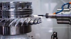
In both Europe and the U.S., vertical turning machines and cells are increasingly producing many automotive brake systems and components, often to remarkably tight tolerances and, in many cases, completely finished.


A U.S automotive supplier machines complete brake disks in three chuckings within a vertical turning cell, consisting of a Hessapp double-spindle DVT 400 and single-spindle DVH 400.


In the first chucking, a double-spindle DVT 400, in an American cell example, machines one side of a brake disk. The traveling spindle then transfers the part to a stationary spindle that cuts the opposite side. Finally, a gripper transfers the brake disk to a single-spindle DVH 400 for finishing.

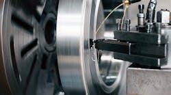
A hydraulic lift-off block tool precision turns a friction ring surface on a vertical turning machine cell in the European example.


In Europe, an automotive supplier machines and grinds complete brake disks on parallel lines of two Hessapp DVT 450 double-spindle vertical turning machines. The second machine in each line is a reverse mirror image of the first.

A twin grinding attachment on a DVT 450 cross grinds both braking surfaces of the disk, as a special-purpose, six-pin clamping device secures the part in the European cell example.
Vertical turning of automotive brake disks, rotors, and hubs has long been the accepted manufacturing method in Europe and is now becoming the norm on this side of the Atlantic. North American suppliers to Chrysler, Ford, GM, Isuzu, and Mazda are following the lead of their European counterparts that supply Volkswagen, Mercedes, BMW, Fiat, Opel, and others.
On such machines as the Hessapp CNC DVH and DVT, an innovative downward-facing motorized spindle permits hands-off loading and unloading, thus eliminating the investment and ongoing costs of ancillary part-handling devices, such as robots. Another advantage of the vertical turning orientation is gravity. Chip disposal, for instance, becomes a non-issue.
Today's verticals have repeatable spindle alignment so accurate, say some endusers, that tolerances commonly associated only with grinding technology are routinely achieved in vertical turning. Also, the process is ergonomically advantageous and generally requires about two-thirds the floorspace of conventional turning arrangements.
Same parts, different cell configurations
In the U.S., a major supplier to Ford, GM, Chrysler, Mazda, and Isuzu produces brake disks in cells of Hessapp 400 series DVTs and DVHs. The DVTs are double-spindle models, while the DVHs are single-spindle verticals.
A single cell consists of a DVT and a DVH linked by material handling conveyors. Typical brake disk machining on the two-machine cells is often done in three chuckings.
The double-spindle 400 DVT machines the first and second chuckings. A traveling spindle picks up the workpiece from an incoming conveyor and positions it above the turret where the bottom of the workpiece is machined. Then, the traveling spindle transfers the workpiece to an upward-facing stationary spindle, positioning it for the top of the workpiece to be machined. When these first two chuckings are complete, a gripper mounted on the cross-slide unloads the part and transfers it to the self-loading and unloading DVH 400 for the final chucking and finishing operation.
Usually a standard flexible conveyor belt links two Hessapps in a cell. This setup accommodates various workpiece configurations— hubs (high and narrow), for example, or brake disks (wide and flat)— by a quick-change adjustment.
In Europe, a renowned German auto manufacturer uses two parallel lines of Hessapps. Each line has two, interlinked double-spindle 450 DVT machines; the second is a reverse mirror-image of the first. This arrangement completes brake disks in four chuckings, which include drilling and CBN grinding.
The first 450 DVT has its traveling motor spindle on the left-hand work area and the stationary motor spindle on the right-hand work area. The drive motor is 68 kW and cranks out 3,200 rpm.
In the first chucking, a three-jaw chuck O.D. clamps on the ventilation groove for roughing the first side of the workpiece. The second chucking roughs the opposite side of the workpiece, while the part is I.D. clamped on the cup.
The left-hand traveling motor spindle loads the right-hand stationary motor spindle. After unloading the stationary motor spindle, a gripper attachment, arranged on the cross-slide, removes and lays the brake disk in the exact position on the workpiece conveyor for the second 450 DVT. There is no need to flip the workpiece between the first and second chucking and/ or between the first and second machine.
The second 450 DVT, as a reverse mirror-image, has its stationary motor spindle at the left-hand work area and its traveling motor spindle to the right.
Hessapps drill and finish the first side of the workpiece in the third chucking. Then the gripper mechanism loads the left-hand work area, in this case, the stationary spindle. The right-hand traveling spindle not only unloads the stationary spindle, but also executes the fourth chucking.
A 12-position turret houses live tools for drilling operations, and cycle times are far below one minute without using multispindle heads. Positioning accuracy for drilling is 60 arc sec, and a high-resolution C-axis motor spindle makes it possible.
During the operation, sintered carbide drills cut at speeds of approximately 100 m/min and feed at 0.2 mm/rev. Higher cutting speeds and/or spindle speeds, required for ceramic drill bits, for example, are obtainable using specifically designed drill heads.
In addition to the drilling process, the cup O.D. and outer face are finished at this time. The workpiece rests in a three-jaw chuck that clamps onto the friction ring O.D.
The fourth chucking involves finishing the second side of the workpiece and subsequent grinding. The brake disk now sits on its cup O.D., secured by a special-purpose six-pin clamping device. Each of these six pins, arranged in an inclined position, can be actuated individually by a hydraulic piston. The device provides low deformation of the workpiece; near immunity to centrifugal force; high speeds; no mismatch with speed changes; and no workpiece lift-off of bearing surfaces. It can also be designed for both O.D. and I.D. chucking.
Once the part is chucked, a hydraulic lift-off block tool with two cutting edges precision turns both friction ring surfaces simultaneously. This same lift-off attachment may also be designed as an NC-controlled unit.
Turning and grinding in one
To meet high demands of quality, tolerance, and surface finish, Hessapp has designed a twin grinding attachment that integrates into turning machines. The attachment, arranged laterally in the working area of the DVT or DVH, can cross grind both braking surfaces. It works with two vertical grinding spindles, which are separately adjustable by an NC axis, and uses cup wheels coated with CBN abrasive.
Two powerful motors (15 kW each) drive the grinding spindles, which turn abrasive wheels 320 mm in diameter up to 3,000 rpm. And the motor spindle's low speed controls the wheel feedrate, while a detector monitors for structure-borne noise. After grinding, a dis-charge belt conveys the brake disk out of the area to a separate balancing machine.
Grinding wheel life per set is approximately 100,000 workpieces. Given the relative cost of grinding spindles, this represents a reasonable production means for finishing brake disk surfaces. This Hessapp vertical turning machine and cell grinding process also achieves flatness tolerance of 3 µm and thickness tolerance of 5 µm in series production.