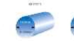
The effect of ambient temperature on a 1-in. diameter steel shaft shows the potential for temperature-drift errors.
This flow chart illustrates how temperature-compensation systems function. Temperature-corrected dimensions allow parts to machined directly to final size.
The gage you use to check your product may be precise, but is it accurate? Perhaps not as accurate as you think, according to Paul Sagar, president of Albion Devices Inc., Solona Beach, Calif., a manufacturer of temperature-compensation systems.
Despite repeatability and reproducibility variations of less than 10%, some gages, even those used in controlled conditions, can be inaccurate due to temperature-induced drift, Sagar says.
Over the long term, temperature drift can cause uncorrected gages to produce varying dimensions, and given today's tighter tolerances, those errors may make the difference between a useable item and a piece of scrap. And according to Albion, thermal drift is the largest single cause of error in precision dimensional measurement systems.
Getting the drift
Just what causes temperature drift? It's a simple law of physics. When metals get hot, they expand. When they get cold, they contract. And different metals expand and contract at different rates. Usually, the gage and the workpiece don't react at the same rate to changes in temperature; this can result in inaccurate gage readings.
For example, steel expands at an approximate rate of 6.8 ppm per degree (F), and aluminum at a rate of 13 ppm per degree. However, one gage that Albion tested expanded and contracted at the rate of 33.3 ppm per degree.
As a gage fixture expands, its measuring probes must extend to contact the workpiece, causing the gage to indicate that a part is smaller than it actually is. On the shop floor, this could lead to acceptance of oversized parts. And in a system where automatic feedback controls the machining operation, the gage would actually tell the machine to produce oversized parts.
Some may argue that changes in ambient air temperature will affect both a workpiece and a gage, offsetting any errors. According to Albion's research, this argument has several flaws. First, washers, coolants, and machining all impact the temperature of a workpiece. Consequently, the workpiece's temperature is often not the same as that of the gage; this results in an inaccurate measurement. Tests performed on a 4-in. I.D. bearing race grinder prove that point. The races hit temperatures of up to 150° during rough grinding, even while flooded in coolant. During the finish-grind cycle, temperatures only dropped to about 120°. The very first ISO standard, written in 1951, fixes the standard reference temperature for industrial length measurement at 68°. Therefore, any measurements made at temperatures other than 68° are suspect if compensation is not made. Measurement errors greater than 0.001 in. can result from that wide of a thermal swing on a part of that size.
Testing for temperature drift
A shop can easily check if temperature drift is a problem It should first measure the same feature on a workpiece repeat-edly, using the same gage over a period of a few weeks and recording each measurement. If a thermometer is available, the shop should also write down the ambient temperature. After taking several readings, it can compare them.
One major auto manufacturer followed a similar test and found surprising results. Measuring the same crankpin on the same crankshaft 60 times over a period of two weeks, the carmaker found that measurements varied by up to 13 µ on a workpiece with a 14-µ control limit, an almost a 100% variation. The gage used for this test was certified to have a repeatability and reproducibility rating of better than 10%. But the problem with gage repeatability and reproducibility as well as process-capability studies, says Sagar, is that they are performed over a short period of time, or in a temperature-controlled environment, effectively eliminating temperature variation. However, according to Albion research, the majority of shop floor gages face significant temperature variations. In fact, shop gages may easily see 9 to 18° temperature changes between early morning and noon, particularly in summer.
Handling the problem
Thermal-drift errors can be handled in two ways. One, the environment can be controlled by maintaining a constant temperature at all times. This is a costly proposition at best. Another option is to use temperature-compensation systems. Temperature-compensation systems consist of a microprocessor- based controller equipped with temperature sensors and a selection of I/O ports that communicate with electronic gaging systems over analog or digital inter-faces. The sensors monitor the temperature of the part being measured, the gage fixture, and the calibrating master during the gaging operation.
The systems can be programmed with the effective coefficients of expansion of the gage, part, and master. During the measuring operations, the system continuously senses temperature variations and sends a correcting signal to the gage in real time. The gage then eliminates thermal errors and displays the correct measurement. Such systems have been installed on automatic, benchtop, and hand-held gages.
The auto industry currently uses temperature-compensation technology. "It's been very well received," Sagar says, pointing to one of the Chrysler's piston lines, on which the company planned to spend $1 million on a block house to control temperature. "Instead Chrysler spent $25,000 for our temperature-compensation system," he relates. Seven years later, the piston line is performing better than another line where a block house is used.
Among the parts features relying on temperature-compensation technology are aluminum engine cylinder and crank bores and piston pin bores. Other features include piston skirt O.D.s, engine crank bores, bearing races, throttle body I.D.s, and hub/bearing I.D.s.
Sagar admits temperature compensation may not work for those applications where a lot of different parts are produced or where the specifications on work change regularly.
However, production facilities that produce the same tightly toleranced part to the same specs for an extended period of time are the best suited for temperature-compensation technology.
"For a line where you build the same piston the same way for seven years, it's ideal," Sagar explains. Perhaps that's why the auto industry was one of the first implement the technology, but it is also widely used in bearing production, printing, and in the railroad industries.
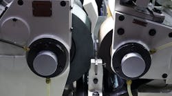
Recently, the reach of tempera-ture-compensation technology has increased, and it can now be found on in-process gages for applications such as grinding and honing. These systems actually sense the temperature of the parts being machined and of the in-process gages during the machining operation. They then provide a correcting offset signal to the gages. The result is that dimensions are measured as if the temperature was a constant 68° while operating temperatures may be considerably different.
Use of the system can save machine time as well as ensure accuracy. Since the system is displaying the size a part would be at the reference temperature, the workpiece can be machined directly to final size without cooling it before making final measurements and performing a finishing grind.


