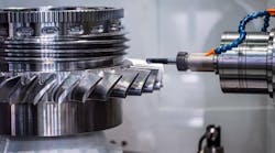
REDUCING vibrations in machining increases tool life, produces better machined surface finishes and prolongs the life of machine tools. In addition, smooth-cutting machines make for a quieter, more pleasing work environment. Chatter is the result of self-excited vibrations in the cutting tool or in the workpiece, and it produces noisy operations and the obvious rippling of finished surfaces.
Vibrations stem from several machining variables, including long overhangs, the combination of high spindle speeds and low feedrates, hard materials and depths-of-cut that may be either too great or, conversely, too shallow, or working with thin-structured parts. Parts have become more complicated, and machining operations today are required to be faster without allowing for the repositioning of workpieces. So tooling with long overhangs increasingly are used to reach all the surfaces to be machined in one mounting. That tends to increase vibration. However, a rule-of-thumb that helps to squelch undue vibration is that when total tool length, from the gage line to the lowest point on the cutting edge, exceeds 4 to 5 times the diameter at the gage line, tapered or tuned tool adaptors should be used.
For example, inside Sandvik Coromant's (www.coromant.sandvik.com/us) Coromant Capto damped milling adaptor, a heavy tuning bar is suspended on rubber bushings and surrounded by a proprietary oil. When variations in cutting force cause the tuning bar to vibrate, the dampening system is activated, and the movement energy of the bar is absorbed into the tuning system.
Most tools are designed for maximum metal removal rates, their designs can make them prone to developing vibrations and chatter. Roughing tends to produce chatter because the primary goal is to remove large volumes of material with each cut, and the vibrations induced by the cut become transformed into the heavy skips that produce the bumpy surface features. Additionally, these resulting vibrations take a toll on the longevity of both machines and tooling. In semifinishing and finishing operations, where the effects of chatter on machined parts become more significant, speeds, feedrates and depths-of-cut can be adjusted to reduce vibrations and chatter.
Newer cutting-tool geometries produce chip loads that are light initially but that increase as the tool or insert bites deeper into the workpiece. This results in removing a sizeable amount of material with a cut, but these new geometries keep the cutting action smooth and progressive without producing heavy vibrations.
In addition to the vibrations that come about from the action between the cutting tool and the workpiece, vibrations also arise from factors inherent in the machine tool, such as slack that develops as machine components wear. Thus, older machines tend to produce more vibrations than newer ones.
Coping With Chatter
Some shops find that they can get a job to run without chatter in their shop, but when they send the tooling and fixturing to another shop, it does not run well. The problem could relate to a difference in the rigidity of the machines they use. "You have to dig deep into the various elements of a machine to discover what is causing vibrations. It could come from worn ways, it could be the interface between the adaptor and the tool, or in the spindle bearings," says Jim Minock, product manager milling at Seco Tools Inc. (www.secotools.com). Once the source of the problem is identified, things can be done to improve the conditions, and reduce or eliminate the vibrations and chatter.
In one example, the source of offending vibrations was a motor mount at the rear of a machine. The bad motor mount allowed the motor to move a couple of millimeters, and a tuned-mass dampener added to the motor eliminated the problem, Minock said.
When it comes to machines, bigger is not necessarily better. It is the rigidity of the machine that counts. For example, one shop was running a job well on a small lathe, but when it transferred the job to a larger machine, chatter developed. In analyzing the problem, the shop found that the smaller machine was more rigid than the larger machine.
When chatter develops, shops can spend a lot of time and effort trying to determine how to deal with the problem, and how to develop the correct speed and cutting parameters to eliminate it. Operators often try to correct the problem by using over-rides for the spindle speed or feedrate on the machine, thinking that moving them slightly will eliminate the problem.
However, most override detents are set at 10 percent of full value, and the chatter-free, "sweet-spot" speed may be between adjacent detents, meaning operators can not adjust to the point where they need to be. This is particularly true when operating at high speeds. For instance, at 10,000 rpm, a 10 percent increment of speed adjustment is 1,000 rpm, but a speed adjustment of 750 rpm may be necessary to find the sweet spot.
So, locating the source of vibrations and reducing their effects can be a daunting task. Often, finding the solution can be counterintuitive, as in the previously cited job in which the larger machine was actually less rigid than the smaller machine.
Steven Jean, milling products manager at Emuge Corp. (www.emuge.com) suggests another example: When chatter develops, most operators tend to slow down spindle speeds and feedrate. This could be exactly opposite of what should be done.
"Often, when vibration and chatter develop with modern carbide tools in extended-reach applications, the tool needs to feed faster into the cut so a little flex is put into it to engage it into the cut," Jean said.
"For example, if a long tool spins fast in the air, but not in a cut, the tool tip tends to wobble and yaw." If that tool starts to cut under the same conditions, that wobble and yaw can continue in the cut and, with too slow a feed, the tool could continue to wobble, fly out of the cut and vibrate.
"Pressure from an increased feedrate settles the tool into the cut and smooths its operation," Jean says.
"Also, some shops have experimented with various combinations of parameters and found they could increase the effectiveness of machining by boosting spindle speeds while eliminating excessive chatter," he adds. The combinations of parameters could appear at harmonic frequencies at which cutting is smooth. For example, a tool may cut smoothly at a spindle speed of 12,000 rpm and again at a spindle speed of 20,000 rpm, but it could create chatter and vibrations at speeds in between.
High speed machining that uses high spindle speeds combined with light cuts may seem to be more vibration friendly than cutting at slower speeds but with heavy cuts, and could result in high productivity with less wear and tear on the machine and cutting tools. However, that same high speed machining with light cuts also could produce highfrequency, low amplitude vibrations that would be detrimental to producing a fine finish. n
What Does It Mean?
- Free vibrations result from a disturbance to a system, such as axis reversal or cut entry or exit. Because machine tools and cutters usually are designed for stiffness, the effects of free vibrations usually are minimal except in some high accuracy or finishing operations.
- Forced vibrations are caused by a consistent, repetitive force, such as spindle imbalance or tooth impact frequency.
- Unstable vibrations result when an excessive amount of energy or work is applied to a structure causing it to self-excite or enter an unstable vibration condition.
- Chatter in machining is a self-excited vibration of a workpiece and/or tool. The poor workpiece surface finish resulting from these unstable vibrations is commonly called "chatter."
- Resonance is a condition in which a vibrating system responds with maximum amplitude to an alternating driving force.
- Critical speed is a characteristic speed at which a predominant response occurs at resonance. In the case of a rotating system, the critical speed is the speed that corresponds to a resonance frequency of the system and may also include multiples and submultiples of the resonance frequency.