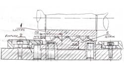
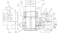
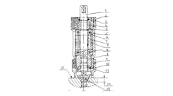
My idea is for creating hob teeth profiles directly on gear-milling machines to cut details such as gears, sprockets, gearbelt pulleys, straight-sided spline shafts and disks with straight splines. Often, calculating the forms of hob teeth profiles using mathematical formulas or graphical methods involves a lot of tweaking.
I call my method for producing hobs the "reversible MLG method." Instead of installing a hob on the mandrel in the gear machine's spindle, I mount a blank (usually soft tool steel) with the same O.D. and length of a real hob. I then turn the blank to match the thread helix of the desired size hob.
Then I install a broach on the gear milling machine's table. This broach looks like a straight-sided spline shaft with teeth. Designed with standard rules, this broach must have sharp teeth with enough chip clearance between the spline and teeth. I set the blank's and broach's speeds and feeds and run in a typical gear-milling process.
After finishing this process, the hob blank has the same helical thread coils as a real hob's teeth. I continue to use the typical technique for producing hobs until the blank is complete.
Mark Grizotsky, Ontario, Canada


