For the best results, pay attention to the details.

Successful HSM requires coordinating the capabilities of machines, their controls and tooling, and programming software.

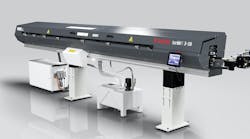
Johnford Hi-Net DCM series machining centers feature double-columns (bridge mills) with boxways in Y and Z and roller-type linear ways in X for high-speed machining of medium-to-large workpieces with heavy table loads.

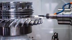
With coordinated HSM techniques, an OSG Tap & Die ballend rib tool, and 20,000-rpm spindle, a shop cut each rib on this mold component in less than five minutes, as compared with taking hours to EDM the same part.

To realize the benefits of high-speed machining (HSM), shops must evaluate and optimize the entire production process: the machine tool, its spindle and tooling systems, and its programming software. Success, according to Steve Ortner, president of Absolute Machine Tools in Lorain, Ohio, rides on systems designed for HSM with complementary capabilities, rather than standard ones modified with high-speed options.
Machine tools for HSM must have rigid structures that dampen vibration, provide stiffness, and resist flexing under high-acceleration rates. Those that are heavily ribbed cast iron and optimized through finite-element analysis, dampen vibration and deliver optimum tool life and surface finishes.
A double-column design is ideal for medium to large-sized HSM machines. This is because the Y and Z axes are fixed loads, and table loads are the only variables.
In contrast, C-frame machines, with X axes on top of Y axes, have two axes with variable loads that are influenced by changes in table loads, making the machines difficult to tune and control. However, with small to medium-sized machines, table loads are typically rated under 1,500 lb, so a C-frame design is controllable and cost effective.
With linear-way machines, the weight rests on bearings, so controlling and tuning the machine for high speed is easy. On small to medium-sized machines with low-torque spindles, linear-way systems perform well. But on medium-to-large machines with high-torque spindles, Y and Z axes are usually boxways, and X axes are linear ways.
Large-diameter machine ballscrews prevent flex and vibration for HSM. Ballscrews should be pretensioned to remove thermal deformation, eliminate growth, and promote axis rigidity. If a machine structure cannot support pretensioned ballscrews, the ballscrews must be cooled by a circulating fluid, which creates maintenance issues.
A machine without pretensioned ballscrews must have scales for accuracy but may still lack axis rigidity. Long-travel machines with long ballscrews should have fixedscrew/rotating-nut arrangements to prevent screw whip, and servomotors should directly couple to ballscrews with a rigid coupling.
Because of HSM's rates of acceleration, counterbalancing with counterweights is not feasible. A large servomotor with no counterbalance or a hydraulic-counterbalance system must be used.
Controls, motors, and drives
Controls, servodrives, and motors work together for optimum speed and reliability. Several considerations are basic for choosing a control/ motor/drive system for HSM:
- Control speed is the ability to process blocks of three-axis-movement information, execute them through the servosystem, and get closed-loop feedback.
- Block look-ahead is the number of blocks the control is looking ahead in the program for vector changes so it can adjust feedrates to avoid over-shooting and gouging. The faster the control, the more blocks of look-ahead are required.
- Automatic acceleration/deceleration, combined with block look-ahead, automatically reduces feedrates to maintain contour accuracy and integrity.
- Mass program storage and an Ethernet interface with a hard-disk drive or ATA card is necessary to run directly from memory. RS-232 DNC modes are not fast enough, says Ortner.
- Large AC digital servo motors and drives are necessary to quickly start and stop HSM machine tools.
- High-resolution feedback with encoders or linear scales are necessary to know where the machine is, where it has been, and where it's going.
- Servo tuning to match machine-axis-inertia changes as table loads change is extremely important. The control must be tuned for various levels of precision versus speed.
HSM Spindles
Spindles driven by belts from a gearbox are limited to 12,000 rpm in a 40 taper and 8,000 rpm in a 50 taper because of belt noise and vibration. This spindle arrangement produces high cutting forces and torque, but it has slow acceleration/deceleration times in production machining and mediocre thermal stability. However, it is an inexpensive drivetrain with low repair costs.
In isolated-direct-drives (IDD or DDS), spindle motors sit on top of spindles and connect with precision couplings. This arrangement handles speeds to 20,000 rpm.
Unlike gear/belt-drive systems, where users attain higher speeds with low-speed motors by changing pulley ratios, spindle motors in IDD or DDS systems run at the same speed as spindles. These systems have good acceleration/deceleration qualities (similar to those of integral spindles) and thermal stability.
According to Ortner, the best systems for high speeds and low vibration are integral or motorized spindles where the spindle shaft is the rotor and the spindle housing is the stator. Typically, speeds range from 15,000 to 40,000 rpm. These are expensive spindles with high repair costs, but they deliver thermal stability with little deformation, exceptional acceleration/deceleration, and adequate cutting torque.
High cutting torques require large spindles and motors, but result in slow speeds. As cutting speeds increase, spindle bearings and shaft diameters shrink resulting in loss of rigidity and limitations on the type of cutting tools used. Also, using small tooling systems imposes restrictions on tool length.
Tooling systems
Standard CAT/BT systems with steep-taper shanks have features that may limit their usefulness at high speeds. They depend only on spindle-taper contact for rigidity, and as spindle speeds increase, centrifugal force can open their pull-stud holding systems.
At high speeds, spindle mouths expand slightly due to centrifugal force, thus causing conventional toolholders to move further into the spindle because of constant drawbarpulling pressure. This cutter pull-back changes Z-axis dimensional accuracy.
MCAT/BBT systems improve rigidity because of contact between the machine spindle face and the tool-holder-flange face, as well as contact with the spindle taper. This reduces machine vibration at high speeds and fretting corrosion between the machine spindle and toolholder tapers. However, this type has the same pull-stud-holding arrangement as CAT/BT systems that can limit speed because of centrifugal force.
HSK toolholders are best for high speeds, says Ortner. Unlike conventional shanks, HSK shanks are hollow, and their clamping mechanisms operate from the inside, making the holders impervious to centrifugal forces. Also, because of HSK short tapers, machine spindle bearings are close to spindle noses for high rigidity.
HSK A-type systems work well for high-torque cutting at speeds to 24,000 rpm. HSK E-type holders, on the other hand, do not have the drive slots of A-type systems and thus improve balance at high speeds. This type is well-suited for low-torque finishing operations at high spindle speeds.
Ortner recommends using HSK-100A — the largest HSK holders — for heavy cutting at speeds to 15,000 rpm, HSK-63A — medium-sized holders — for medium to fine cutting at speeds to 24,000 rpm, and small HSK-50E hold-ers for high-speed finishing.
Programming
According to Sean O'Neil, president of Cutting-Edge Technologies, a mold and die shop in Windsor, Ontario, programming is critical for HSM, although often overlooked. This is because operators, trained and familiar with software systems already in the shop, fail to investigate others more suited to HSM.
Programming for HSM should provide consistent results in unattended operation — machining a part from start to finish with multiple tools without interruption. Doing so is how some Japanese shops, with labor rates comparable to those in the U.S., compete with Chinese shops with lower labor rates.
Also, if programming software accurately recognizes remaining stock from previous operations, shops progress from rough to semifinish machining without intermediate cutting.
Although time-consuming, preparing a tool database — standardizing data such as speeds, feedrates, step-downs, and arc-in feedrates for various tools throughout a shop — pays rich dividends in determining tool-life expectancy, speeding setups, and avoiding tool collisions.
A constant chip load is the key to maximizing tool life and generating precise surface finishes. Programming extra passes when cutting into a corner controls chip load and prevents tool deflections. For consistently high cutting speeds, programmed arcs eliminate the need for machines to decelerate going into corners and then re-accelerate coming out of them.
Ortner believes the most important factor is knowing the average incremental point-to-point distances generated by a CAD/CAM system. These distances are shrinking as shops increasingly rely on machines for producing good surface finishes, rather than having employees benchworking and polishing parts. For example, most mold shops will rough with a 0.010 to 0.040-in. average-distance movement and finish with a 0.002 to 0.010-in. movement. Average control feedrates are determined from average distance movements, which take into account long, straight moves that could be several inches between points and tiny 0.001-in. detail moves.