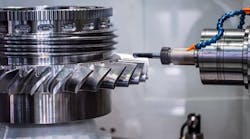
Microcomponents usually are manufactured using molds that must be micromilled to achieve the accuracy required.
Photo courtesy of Cimatron.

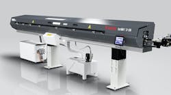
Alpha 2 Plus Micro drills from Titex Precision Cutting Tools (www.titex.com) are externally cooled and have an optimized flute and tip geometry. The new range offers 80 dimensions in diameters from 0.5 mm (0.019685 in.)
to 2.9 mm
(0.1141732 in.).

CimatronE software has built-in high-speed cutting strategies and other dedicated machining functions optimized for micromilled surfaces.
Not only are the parts getting smaller, they are packed with more components to provide added power and functionality. Manufacturing small, complex parts requires machining with microtools that are delicate and can be easily deflected and broken. Cutters for micromachining do not respond to their cutting environment as their larger-size cousins do. There are a number of micromachining issues that influence the underlying mechanisms of the process, and are fundamentally different than when machining with large tools. These include changes in the chip-formation process, changed cutting forces, unusual vibrations and instability in the process and the generation and character of the resulting machined surface.
SHRINKING PARTS, GROWING APPLICATIONS
Miniature components have a wide variety of applications in aerospace, automotive, biomedical, electronics, information technology, optics and telecommunication industries. To keep cost down, most microcomponents are manufactured using molds. Mold makers face diverse challenges, ranging from the use of exotic materials to special mold coatings, milling parts with 0.002-in. (50-µm) diameter tools, EDMing with wire diameters of 0.00078 in. (20 µm) and achieving submarine accuracy. Parts are being designed with feature sizes of less than 100 microns — somewhat larger than a human hair.
With such small part and feature sizes, accuracy takes on a new meaning. For example, a ±0.0002-in. (±5-µm) tolerance is very different in relation to the size of a feature on a part that is 0.2 in. compared with a feature on a part that is 0.002 in.
"To achieve the quality and accuracy required in micromachining, while meeting economic and commercial constraints, the entire manufacturing chain must be optimized and synchronized," says Hari Sridharan, director of engineering at Cimatron Ltd. (www.cimatron.com), Givat Shmuel, Israel , a provider of CAD/CAM software. At a time when the production of simple and medium complexity molds is shifting to countries with low labor cost, U.S. and European moldmakers are turning to more advanced technologies such as micromolds and micromilling to remain competitive.
SMALL PARTS, BIG CHALLENGES
Among the major challenges is the direct milling of miniature-part molds and manufacturing of EDM microelectrodes. Challenges related to micromilling include the use of miniature tools with diameters down to 100 µm or less, spindle speeds of up to 150,000 rpm and surface finishes as good as 0.2 µm. (0.0000078 in.). And, since polishing is often impractical for fine parts with microdetails, micromilling calls for polishless machining.
WHY MICROTOOLS DEFLECT AND BREAK
Tool deflection and breakage is much more frequent when micromilling as compared with conventional milling. Ken Yap, director of Suwa Precision Engineering Pte Ltd in Singapore (www.suwaprecision.com) explains the three main reasons why micromachining tools are more apt to break.
First, when metal is removed by machining, there is a substantial increase in the specific energy required as the chip thickness decreases. This means that in the case of micromachining, as the chip gets thinner with smaller depths of cut, the microtool bit is subject to greater resistance as compared with conventional machining. It is as if the workpiece material becomes harder during micromachining. This resistance force is strong enough to exceed the bending strength limit of the tool bit even before the tool experiences any significant wear, and that can lead to breakage of the tool bit. One way to prevent this is to ensure that the chip thickness is smaller than the radius of the tool bit edge.
Second, a sharp increase in cutting forces and stress from chip clogging during the micromilling process can also cause the tool bit to break. In most micromilling operations that use a miniature microtool bit with two cutting edges, each cutting edge removes chips from the machining area only within half a rotation. However, if chip clogging occurs, within a few tool rotations the cutting forces and stresses increase beyond the limit of the bending strength of the tool bit, and it will break. For this reason, some users prefer high-speed steel tool bits because they are more flexible and tolerate clogging better than carbide tool bits.
Third, the tool bit tends to lose its cutting edge due to built-up edge, and cannot machine efficiently. As the workpiece starts to push on the tip of the tool bit, the tool bit deflects slightly. The increase in tool deflection and the stress generated by milling with every rotation eventually cause the tool bit to break. This process is also called extensive breakage.
As a result of these phenomena, most micromilling machines are sold with sensors to measure the forces acting on the tool bit, and advanced CAM software to predict the chip load throughout the micromachining process.
CAD/CAM REQUIREMENTS
Milling machines, holders and tools cannot simply be scaled down to achieve the microscopic dimensions and extreme accuracy required by micromachining, In the same way, software must be tuned and optimized for microprocesses. Creating and modifying geometry with the right accuracy, smoothness and continuity are just the entry points for a microcomponent CAD solution. CAM systems must be able to handle the tight tolerances and ultra-accurate machining. Since operators cannot interfere to prevent tool breakage, the software must consider the chip load accurately throughout the machining process.
Cimatron has introduced a NC software solution for micromilling that is available on the CimatronE 7.0 product suite. At the time of its release in 2005, the company said the software was the first commercial solution for micromilling. The software is a product of Cimatron's participation in a micromilling research project funded by the European Community and sponsored by the Fraunhofer Institute for Production Technology (IPT) in Aachen, Germany.
Because hand polishing is not an option in micromilling, Cimatron software supports high-speed milling for polishless machining. To eliminate the risk of tool breakage, reduce air-cutting motions, maintain tool load and lengthen tool life, the software constantly and automatically records remaining stock details, even at the microcomponent level. The software supports five-axis tilting to machine deep areas with conic tapered tools. The ability to tilt a tool away from the material enables using shorter tools. However, since continuous five-axis milling is currently less accurate than three-axis milling, machine specifications and actual performance must be carefully validated when using continuous five-axis for micromilling. Other features of the software include an optimized milling strategy and built-in CAD with accurate (0.001 µm) surface creation and mending tools.