Advanced grinding technologies tackle hardened steel components.

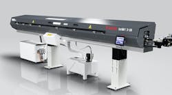
A high-speed centerless grinder equipped with CBN wheels boosts productivity in an application involving camshaft bearing seats.

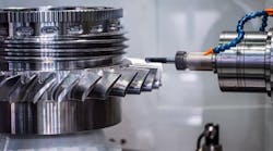
In this example of angle plunge-cut grinding, three wheels tackle a camshaft, each performing different operations in a single pass.

This illustration shows a grinding-wheel profile and characteristic values for high-speed peel grinding: bs Spark-out represents the parallel-contour zone for finishing, and bs Angle is the tapered roughing zone.

This figure shows the difference between high-speed peel grinding and fine hard turning of a flanged shaft. The cutting speed was 150 m/sec; oil was used as the coolant.
Before deciding whether or not to hard turn or grind workpieces over 45 Rc, shops should ensure they're comparing "apples to apples" — current technology to current technology. Instead, many evaluate the latest turning centers versus outdated grinding systems. That's a mistake because, while hard turning has its benefits, today's advanced grinding machines, ultra-efficient grinding wheels, and other technological innovations also provide a sound basis for rapid, adaptable, economical machining.
Centerless plunge-cut grinders are particularly well-suited to high-volume, long-run production — especially when teamed with crystalline-boron-nitride (CBN) wheels. In fact, these machines are built to use CBN, employing features such as Granitan machine beds, which absorb vibration and maintain thermal stability, and stiff grinding spindles, mounted in bearings at both ends, that deliver peripheral speeds to 120 m/sec. Lubricant mist, which forms at these high speeds, can be extracted under vacuum and separated from the working enclosure.
Buying sets of CBN wheels can quickly add up, but this cost is often justified by their durability and productivity. For instance, it's not unusual for a set of wheels to process over 500,000 camshafts. Compared to conventional abrasives, CBN lowers the costs of grinding wheels per workpiece and prolongs the service life of regulating wheels thanks to a reduction in grinding forces.
In an example involving bearing seats for cast-steel camshafts, a centerless external-cylindrical grinder rough grinds five bearing seats to the specified machining allowance of 4.1 mm in 12 sec. This level of efficiency eliminates the need for preliminary turning.
In the case of finish grinding, fine tolerances must be achieved for diameter and roundness and low degrees of roughness; therefore, it's a good idea to use centerless-cylindrical grinding with CBN wheels that have coatings in a ceramic bonding, which can be re-profiled. The advantage is that these wheels are profiled when mounted and can be made to run true. In use, particularly at high speeds, they deliver high throughput and surface quality. Also, profile wear and changes in roundness take place more slowly than with conventional grinding wheels and are counterbalanced by the longer intervals between dressing operations.
Plunge-cut grinding
If bearings have to be ground to precise standards of rotational accuracy, machining between centers is essential. Clamping between centers places the workpiece in a specific position for grinding of cams, plunge cutting of grooves, and machining of plain shoulders.
In the illustration, a set of grinding wheels performs angle plunge-cut grinding of a gear shaft. Three individual wheels, mounted as a set measuring 153 mm in width, machine seven bearings and one shoulder in a single pass.
This application calls for sintered-corundum grinding wheels. That's because CBN wheels cost considerably more, and profiling over this width would prove expensive. Even an increase in the throughput rate for rough grinding, which could cost-justify CBN, is subject to strict limits. The machining allowance is so small that the roughing time accounts for only a small portion of total cycle time.
A reasonable proportion of total cycle time is required for finish machining to ensure dimensional and geometric accuracy. At this point, a particular advantage of plunge-cut grinding becomes clear. The deformation of the machine and work-piece caused during roughing is counteracted during finishing and sparking out. This is not possible in the case of hard turning, where the cutting edge of the tool is traveling along the surface line of the workpiece. Below a certain machining depth, turning doesn't remove additional material; instead other processes (reaming and squeezing) shape the surface.
In contrast, grinding machines using sets of wheels can prove economical in long-run, high-volume production. The grinding time is relatively short, and the proportion of setup time per workpiece is negligible. In this example, it would have been impossible to approach the cycle time, machining cost, workpiece quality, or processing reliability with hard turning.
High-speed peel grinding
A particular advantage of hard turning is its adaptability from the standpoint of workpiece geometry. If the geometry is modified, the NC toolpath is adapted accordingly. As a result, a variety of workpieces can be finished in a single chucking with a small number of tools.
High-speed peel grinding (HSP) represents an alternative technique offering considerable flexibility. In contrast to plunge-cut grinding with a profiled grinding wheel, peel grinding performs longitudinal shaping with a narrow, all-purpose CBN grinding wheel. The entire machining allowance of several tenths of a millimeter is removed in a single pass. The CBN coating features an angled roughing zone, 2 to 5 mm wide, which performs the primary metal-removal process. This is adjoined by a zone contoured in parallel for finishing and sparking-out purposes. It is sufficient for this zone to be around 2 mm in width, even for roughness limits of Rz < 3 µ.
Cutting speeds in the range up to 160 m/sec are used in HSP grinding, and even greater than 200 m/sec in individual cases. As with turning, the throughput rate (Qw) is calculated as a product of the axial rate of advance (Vfa), the circumference of the workpiece ( dw), and the radial machining allowance (z/2):

The illustration of the HSP process shows some other important parameters, including the width of the grinding wheel (bs) and the peripheral workpiece speed (Vw). In turning, the peripheral workpiece speed represents the cutting speed and varies within narrow limits dictated by the limitations of the tooling. In grinding, however, shops can optimize the speed within wide limits in the roughing and sparking-out zone.
The metal-removal rate is a characteristic value for the stress loading on the abrasive coating and reaches about 100 mm3 /mm/ s (volume/wheel width/time) in the roughing zone. With a roughing zone bs Angle of greater width, which is limited by workpiece geometries and unavoidable overrun distances, the axial rate of advance can be increased at the same rate as metal removal.
From the standpoint of attainable rates of advance, HSP grinding beats precision hard turning. That's because roughing can be carried out with an abrasive coating of only a few millimeters in width. By contrast, hard turning uses a single cutter, and the chip cross-section is limited to around one and one-half tenths of a millimeter of feed and advance.
The following illustration depicts the throughput rate customarily achieved in the processing of 100Cr6, in which the rates of advance are proportional and the desired degrees of roughness are achieved. The throughput rates for hard turning lie between 20 mm/sec and 70 mm/sec; in external-cylindrical HSP grinding, the rates can reach over 100 mm/sec, and in external-cylindrical plunge-cut grinding can be substantially higher.
In this example, an HSP machine ground the cylindrical faces and radii of a flanged shaft. The particular advantage of HSP grinding lies in the variety of shaping tasks that can be accomplished by a single grinding wheel.
Chucked workpieces
While chucked workpieces appear to be ideally suited to hard turning, grinding should be considered for workpieces requiring internal and external machining. On modern I.D./O.D. cylindrical grinders, these processes can be carried out simultaneously and, in many cases, at faster overall machining times than hard turning. These simultaneous I.D./O.D. grinders feature a fixed-workpiece headstock and two compound slides on which an external and internal grinding spindle travel. A typical application for these grinders is the machining of a gear-wheel made of heat-treated steel. Workpieces are presented to the chuck by a handling mechanism with double grippers, centered by the previously finish-machined tooth system, and clamped against a plane surface. With this method of chucking, the subsequent grinding operations result in a minimum running deviation of the hole and synchromesh cone relative to the tooth system.
Diametric tolerances are 16 µ for the cone and 23 µ for the hole. Due to the statistical-processing feasibility specified, however, they are limited to around 50% of the nominal values.
Cycle time is around 45 sec, which is determined by the internal-cylindricalgrinding process. A corundum grinding wheel is adequate for the external grinding of the cone. To complete internal-cylindrical grinding in the shortest possible time, a CBN grinding wheel, capable of being dressed at a peripheral speed of 60 m/sec, is used.
The CBN grinding wheel is re-profiled after every 100 work-pieces. Dressing accounts for around 6 µ of the diameter of the wheel, and the process is monitored by an integrated noise sensor. This results in a consistent, reliable grinding process at negligible tool costs.
Other Grinding AdvancementsMany grinding systems are now combining cutting and grinding into a single platform. The benefits of this multitasking approach are improved workflow, reduced setups, fewer machines and operators, and higher, more-predictable part quality resulting from performing all operations in one setup. Grinding-machine builders are also attempting to reduce the costs incurred by the use of metalworking fluids. For example, they're using shoe-type nozzles, closely matched to the grinding-wheel profile, to lubricate the gap between grinding wheels at low lubricant flowrates. This arrangement lets the grinding wheel collect coolant and deliver it to the contact area. With nozzles of the optimum design, it is now possible to reduce the consumption of lubricant by a factor of about five and pump pressure by a factor of 10 — with no loss of grinding performance. Further progress in minimizing lubricant consumption could be made in the development of oil-mist lubrication, although, at present, this is restricted to low to medium-throughput rates. |
Mr. Luetjens is general manager, marketing department, and Dr. Mushardt is manager of the research-and-development department at the Schleifring Group, Hamburg, Germany. The Schleifring companies — Blohm, Ewag, Jung, Mägerle, Schaudt Mikrosa BWF, and Studer — are represented in North America by United Grinding Technologies, Miamisburg, Ohio. More information is at grinding.com