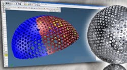
A 3-mm ballnose cutter re-roughs a 50 Rc H13 toolsteel mold at 15,000 rpm and 120 ipm.
High speed spindles are application specific, sophisticated, delicate and expensive. Here is how one manufacturer and supplier ensure high-speed spindles are optimally designed for their applications, and users know how to get the performance they expect while protecting their spindle investments.
The capability of spindles to go fast is dictated by the dynamics of their bearings. The goal of spindle manufacturers is to design with the largest bearings possible, based on spindle speed, to provide maximum stiffness for the application. The faster spindles rotate, the smaller the bearings and spindle shaft must be. That results in decreasing spindle stiffness that imposes limitations on the size, type and length of cutting tools that can be used with the spindle. Also, as speeds increase, available spindle torque decreases.
A 'do-it-all' spindle
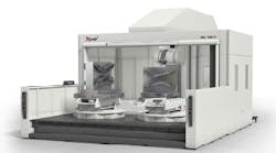
Mold and die shops want to maximize all of the features of a spindle: torque, power and speed, especially with medium-and largesized machines. Steven A. Ortner, president of Absolute Machine Tools Inc., Lorain, Ohio (www.absolutemachine.com), a distributor of CNC machine tools, says the desire for incorporating all of those features leads to an integral, or motorized, spindles that incorporate the motor within the unit. Integral spindles use the spindle shaft as the rotor and the spindle housing as the stator for the electrical motor that drives them. "We feel integral spindles are a must to produce the fine finishes required in hard milling mold and die work," Ortner says. The majority of large machines his company builds for mold and die applications are equipped with 15,000 rpm HSK-A100 integral spindles manufactured by Weiss Spindle Technology Inc. of Mentor, Ohio (www.weissspindletechnology.com).
Integral spindles produce low levels of vibration and have the best thermal stability with little thermal deformation of all spindle types, and are recommended high machining speeds and fine workpiece finishes are required. They have extremely good balance and produce little noise, and have good acceleration and deceleration characteristics. However, they also are the most expensive spindles, and repair costs for them are high.
Most HSK-100 spindles are limited to 8,000 to 12,000 rpm because the large tooling requires correspondingly large spindle bearings, which limit top speed. Normal torque for these spindles is 150 lb.-ft., and at full power they produce speeds of 3,000 rpm to 10,000 rpm. "Our Weiss HSKA100 spindles have a range of capabilities that meet most of our needs," Ortner says. "They develop full power at 1,000 rpm with torque of about 300 lb-ft and motor power of about 50 hp." That low-speed power provides versatility to cut a variety of jobs. The tools can rough cut and can quickly remove large quantities of material with cutters up to 3-in. in diameter, and have enough speed to finish roughed parts.
For the high-speed applications common in mold and die, automotive and aerospace work, the HSK tooling system has become the standard, Ortner says. That tooling system has a toolholding system that clamps inside the tool and expands at higher speeds increasing the clamping force, Ortner says, adding that the short taper on the HSK tooling systems places the bearings closer to the spindle nose, enhancing rigidity.
Designing for speed
Designing a spindle to achieve a certain speed involves more than just consideration of spindle dynamics, says Jeffrey A. Watts, manager of sales and development at Weiss. Design parameters include consideration for cutting characteristics of the workpiece material, the desired cutting speed and tooling limitations. Weiss uses SpindlePro, a computer-simulation program developed by Prof. Yusuf Altintas at the University of British Columbia, to analyze spindle performance, Watts says. The software program predicts deflections on the spindle, contact loads and moments at the bearings and the response of housing supports under any load or cutting force. "We optimize the spindle configuration considering the drive shaft, motor, lubrication style, transmission mechanism, bearing types and toolholder style. Bearing locations are determined to ensure chatter and vibration-free cutting. With this software we determine spindle dynamic stiffness - a combination of static stiffness and damping — power, torque and dynamic characteristics needed to optimally cut the material to be machined, while taking into account the tooling to be used," Watts says.
The program often is used to optimize spindles for shops running long-term machining operations. However, it also can be used to qualify tooling and cutting parameters on existing spindles. "A change in tooling or speed with a specific spindle might make a big difference in performance and productivity," notes Watts.
Checking the parameters
"Just because you have a spindle that is rated for ultrahigh speeds doesn't mean you can run all applications at top speed," Ortner says. "You have to consider the material you are cutting," he adds, noting that aerospace applications typically involve easy-to-cut aluminum in which speeds can be higher than when cutting the hard steel that is typical of many mold and die and automotive applications, and in which limitations on tooling dictate cutting-speeds.
High speed spindles can be damaged by cutting with the wrong feeds, speeds and tooling. Absolute Machine and Weiss developed a software program to help shops determine the cutting-parameter limits and tooling characteristics to prevent spindle damage. To determine the compatibility of the application and the spindle, shops enter the tool diameter, number of flutes, speed and feedrate, radial and axial depth-of-cuts and tool length. The program then determines the bearing overload limit, tooling interface bending moment limit and optimizes the cutting parameters for the application.
Thwarting thermal growth
Thermal expansion of the spindle as cutting progresses can be a problem, particularly to shops that strive to achieve accurate machining to minimize expensive, time-consuming handwork. The thermal expansion of spindles is an issue in mold and die work, and on any job thermal expansion could cause tool crashes that, even when minor, can damage high-speed spindles.
"To achieve high accuracy and minimize operator error, we provide a thermal-compensation system on almost all machines fitted with Weiss HSK-A100 spindles," says Ortner. The thermalcompensation system automatically adjustsfor thermal changes in the X, Y or Z axes based on a thermal-growth map of the machine that is developed prior to machining. The thermal-growth map is produced by comparing data on the location of tooling from an automatic laser tool setter and spindle-bearing temperature data generated by a temperature sensor within the spindle. As the spindle runs up and thermal growth occurs, the system develops a profile of anticipated spindle growth as a function of spindle speed and length of time of operation. This thermal-mapping data is loaded into the machine control, and runs in the background so the operator is unaware of it. "In this way, the control knows that operation at a certain speed for a certain length of time will produce a certain amount of spindle growth. Then, the control adjusts the proper axis to compensate for this growth. A tooling change requires remapping the machine," Ortner says.
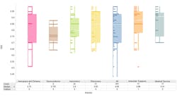
Stable cutting conditions and smooth finishes are produced when spindles are optimized for the application. Variations in tool displacement produce vibration and chatter, resulting in unstable cutting, poor surface finishes and possible damage to workpieces, tooling or spindles. (Chart from Manufacturing Automation Laboratory, University of British Columbia.)
Smart MachiningHigh-speed-machining-intelligence technology from Mikron (www.mikronuus.com), consisting of modules on a high-speed machining center, improves process reliability, optimizes machining performance and allows for unmanned operation. The Advanced Process System (APS) module measures spindle-bearing vibration levels during milling and displays these on a monitor. The color of the display changes according to the range of vibration (g values): 0 to 3 g is green indicating good performance; 3 to 7 g is yellow indicating a process change is necessary to prevent premature spindle or tool failure; 7 to 10 g is red indicating that continuing in this range can cause damage to the spindle, machine, tool and workpiece. APS also sets g limits for warnings and automatic machine stop. Measured vibrations can be recorded for analysis. Another Smart Machining module, called Operator Support System (OSS), allows operators to optimize speed, accuracy or surface finish — the usual considerations when high-speed machining complex 3-D contours. Achieving these target values according to the application requires modification of hidden and usually inaccessible parameters called machine-performance settings that consist of hundreds of related CNC parameters, such as servo-loop gains, axis-jerk values and smoothing filters. With the OSS expert control system and a graphic interface, operators can optimize machine-performance settings through a prioritization of the three target values. A selection can also be made for the complexity of the contour and weight of the workpiece. |

