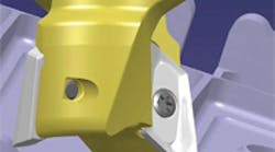
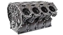
Advanced techniques have emerged for machining aluminum during the past five years,
These techniques are the result of shops looking to maximize metal removal rates, minimize cycle times and reduce machine power requirements.
The development of highspeed machining techniques, combined with fast metal removal strategies, have boosted aluminum cutting speeds to unprecedented feedper- tooth rates.
Equally important, shops have reduced setup times and streamlined processes by combining roughing and finishing operations in a single pass.
These developments have had a particular impact on aerospace manufacturing, where ever increasing demands for improved flight safety also have resulted in stringent standards for the quality of wall-surfaces that call for the elimination of machining-pass mismatches.
Research and development engineers at Iscar (www.iscar.com) have provided the following guidelines to take advantage of advanced techniques for milling aluminum:
Micro-precision tool adapters that provide reliable control of radial and axial axes have a significant role in terms of precision. HSK 63, HSK 80, and HSK 100 toolholders are the options most often recommended for these processes. Using these adaptors guarantee stable performance with minimal runout, particularly when milling deep pockets in aluminum applications. Also, nitrated contact areas on the adaptor assist in maintaining precision work and enhance durability.
Dynamic balance assists in reducing vibration and in improving surface-finish quality, and indirectly extends the spindle-life of the cutter. Cutter bodies should be balanced to meet centrifugal forces conditions of G2.5 or more depending on maximum allowable spindle speed. Dynamic balance is enhanced when cutter bodies are manufactured from high quality homogeneous steel, and by accurately grinding the tool neck.
Also, correct removal of unbalanced mass from the cutter body is necessary to ensure dynamic balance. Special highspeed machining kits consisting of pre-selected and pre-weighted inserts and screws should be used. New screws should be used each time a new insert is mounted on the cutter face.
Maximum speed testing, regulated by the ISO and ANSI standards that dictate the testing procedure of high-speed milling cutters, ensure that the tools can be safely run when subjected to extreme centrifugal forces. Specimen tools undergo such testing to obtain international accreditation. These tests determine the maximum speed that should be used without posing the threat that centrifugal forces might pull the insert out from its position, or shear the head of the holding screw or pose any risk to the machine operator. The standard imposes a 50 percent safety margin factor on the maximal speed value and is marked on the tool shank.
No tool-path mismatch is allowed because safety is the most important concern for the aerospace industry. The surfaces on the wall of pockets must be free from horizontal steps because of the tendency for such steps to generate strain concentrations that could cause cracks. The allowed deviation for smooth surfaces is limited to 0.0004 in. (0.01 mm). The removal of these steps requires a roughing operation followed by a finishing operation, or performing the two operations simultaneously using sophisticated tools. This last option significantly shortens the production process time and consumes fewer tools.
Chip formation and evacuation is enhanced by cutting edges that have high rake face geometries which also contribute to the reduction of machine power consumption. Recently, Iscar R&D engineers designed cutting tool edges that combine shredder and chip-splitter geometries. These designs significantly improve machining conditions by enabling high chip removal rates without increasing power consumption.
Cooling is necessary when machining aluminum. In addition, indexable milling cutters for aluminum should be polished to avoid material build up. At high rotational speeds, there is always the risk that the inner emulsion stream, inside the tool, might not reach the cutting edge because of centrifugal forces.
Therefore, coolant holes should be designed with nozzles pointed directly to the cutting edge. Also, minimum quantity lubricant systems have become popular for aluminium machining applications because of their cost-effective benefits as well as their healthy and environmentally friendly features.
Anti-vibration systems are necessary to reduce chatter, particularly with large protrusions and at high speeds. Chatter reduction results from selecting optimal cutting modes although various chatter reducing cutter designs are available. In some, a combination of steel and tungsten carbide tool material is used.
Because aluminum parts can be damaged and disqualified from sudden tool fatigue failure, it necessary to know and control total length of tool usage.
