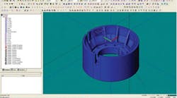
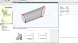
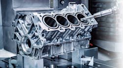
ESPRIT CAM displays a working model of the aluminum-bronze cylindrical gas turbine engine vane.
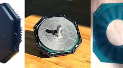
A detailed view of the cylindrical gas turbine engine, showing the numerous ribs that made machining so time-consuming.
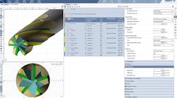
A 0.75-in., indexable insert ball nose end mill was used for semi-finishing, and finishing was performed with a 0.5-in. ball nose end mill.
Johnson Brass & Machine Foundry in Saukville, WI, uses a patented centrifugal casting technology to convert cast and wrought alloys into "formings." It produces an impressive range of shapes and sizes — including balls, stators, seals, valve bodies, gears, large flanged bushings, vacuum chamber liners and medical imaging mainframes — in pure copper, cast and wrought aluminum, Monel, nickel silver, chrome copper, copper silver, zirconium copper and stainless steel. And, the formings are machined to customers’ specifications.
Every month, JBM creates about 40 computer numerical control (CNC) programs for customer parts. Recently, the primary machining for one part involved using a 3-axis horizontal milling machine to remove material between a series of "ribs." The original CNC program would have taken about 22 hours of machine time to execute the task. Using DP Technology’s ESPRIT programming software, Johnson technicians re-programmed the part, substantially reducing the machining time and, based on a machine rate of $95 per hour, saving $41,000 to complete the customer’s order.
JBM’s centrifugal technology applies extremely high centrifugal forces to molten metal throughout the solidification and thermal contraction phases. The centrifugal force drives any impurities to the bore, so it can be removed by machining. The water-cooled mold wall applies unidirectional chilling of the metal. This allows the material to undergo directional solidification, imparting optimum strength for ring and cylindrical structures. The uniform directional advance of the solidification transformation also provides a cleansing effect, as impurities float ahead of it toward the riser area of the bore. As a result, JBM’ castings meet and exceed all physical properties typically found with forgings and forged metals. And, the castings maintain excellent physical properties multi-directionally, throughout the component.
CNC programming challenges
JBM has about 20 CNC machine tools installed, including two Toshiba TMD-20 live spindle vertical turret lathes, a Hermle 5-axis machining center, and two Toshiba BTD-110 3-axis horizontal machining centers. The company currently has two full-time CNC programmers.
JBM’s first CNC machines were programmed manually. When Thomas Kempke, JBM vice president of manufacturing, joined the company one of his top priorities was to improve its CAM programming capabilities. The CAM software used by Kempke’s previous employer had been developed by one of the major product lifecycle management (PLM) software companies.
"The CAM software I was familiar with worked well, but it is very expensive," according to Kempke. "I was hoping to find a versatile but less expensive solution that could improve the productivity of all our machines, both turning and milling. I looked at a number of software packages and found that most had glaring weaknesses, such as limitations in producing programs for 5-axis machining centers. But ESPRIT works very well on all of our machines and offers very powerful 5-axis machining capabilities."
ESPRIT’s 5-axis supports any combination of rotary tables and tilting heads, with the ability to perform simultaneous 5-axis cutting, or 3+2, where the part is rotated to orient it into place, and then the material is removed with 2.5 and 3-axis operations. ESPRIT provides tools and machining cycles for free-form roughing, Z-level machining, finishing, re-machining and more in either 3-axis or simultaneous 5-axis.
Example of turbine vane
"ESPRIT has helped us substantially improve programming capabilities, primarily by enabling us to reduce machining cycle time and programming time," Kempke said. He pointed to the example of a part that was centrifugally cast and then machined to the customer’s specifications on the company’s BTD 3-axis machine. The aluminum-bronze part is a cylindrical gas turbine engine vane that has a large number of ribs. Johnson started by importing the solid model of the part provided by the customer into ESPRIT.
The programmer selected a zigzag machining strategy, using a face mill for roughing out the part. He used a separate toolpath to cut out the area between each adjacent pair of ribs by creating a rectangle that defined the limits of each area to be machined. The zigzag strategy offers fast cycle time and excellent quality along vertical walls. This cycle optimizes the tool path by rounding internal sharp edges for high-speed cutting and providing G-Code output using G2/G3 circular interpolation whenever possible. The programmer used a single-direction strategy for finishing while taking advantage of ESPRIT’s rest machining capabilities that automatically develop an efficient method of removing the large amounts of material often required to cut castings to their final specifications. A 0.75-in., indexable insert ball nose end mill was used for semi-finishing, and finishing was performed with a 0.5-in. ball nose end mill.
Rest machining makes it possible to re-machine previously uncut areas of the model, resulting in a constant volume of remaining material. The toolpath is optimized based on the results of the previous machining cycle to eliminate air cutting and minimize retract movements. Optimized re-machining is achieved by always monitoring the in-process stock model to know where the remaining material is at all times, even when machining undercut areas. ESPRIT automatically optimizes the roughing toolpath by, for instance, rounding sharp angles and fluent stepover with chordal feed to avoid straight paths, enabling climb milling in all situations. The dynamic in-process stock model, which optimizes the toolpath, can calculate the toolpath from outside to inside (collapse) or vice-versa (expand). This module also offers a wide range of approach/retract positions. This feature helps to substantially reduce cycle time compared to traditional CAM programming methods.
Machine time reductions
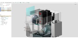
The programmer then viewed a simulation of the machining operation with the goal of identifying potential opportunities for improvement. He was able to view the entire machining environment, including stock materials, fixtures and clamps, in dynamic, solid-shaded graphics. All the kinematic action of the machine was displayed in "real time," enabling accurate visualization of the entire machining process, machine movements, and material removal. He used the software’s built-in part inspection to compare the original "as-designed" part to the "as-machined" workpiece to assure part accuracy.
In this case, the programmer noticed that the tool was cutting air during a significant portion of the cutting cycle. The program was following his instructions by cutting out the boxes that he had used to define the area between each pair of ribs. The simulation revealed that the problem was that the area to be machined between the ribs was highly tapered, while the programmer had approximated its shape as rectangular. The air-cutting occurred when the program cut out a much larger than necessary area around the pointed side of the taper.
The programmer solved this problem by changing the toolpath definition to consist of a series of stacked rectangles that he progressively reduced to match the contours of the taper. This change alone reduced cycle time from the original 22 hours to 17 hours. The programmer also noticed in the simulation the potential for further improvements by increasing the Z-axis stepdown in the finishing operation. He tried several different values and each time viewed the simulation to determine the size of scallop on the surface of the part. He determined that he could increase the stepdown and still meet the surface finish specifications, further reducing machining cycle time to 14 hours.
The programmer generated additional timesavings by increasing feeds and speeds, increasing stepdown value on the semi-finishing operation and cutting only the corner rather than the entire wall in rest machining. These changes further reduced the machine cycle time to about 11 hours. The resulting 50% reduction in machining cycle time provided a proportional savings in the cost of machining the part.
"The time savings that we obtained on this part are only a bit larger than the typical savings that we are able to achieve by using ESPRIT to optimize machining operations to improve cycle time," Kempke said. "We have also seen substantial reductions in programming time. As a result, we have been able to improve our competitive position by providing cost and delivery lead-time improvements to our customers."
