Box or linear guideways—some say it's old versus new school or strictly customer preference. In any event, most people in the machine tool and bearing industries agree that the application should be the deciding factor.
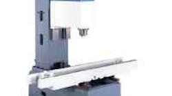
In an effort to better match machine to application, Fadal manufactures its A Model VMCs with all boxways, all linear guide-ways, or (as shown) a combination of both. (See "Which way is right?", AMERICAN MACHINIST July 1998, pg. 72-76.)
Giddings & Lewis uses boxways with non-metallic liners running on replaceable hardened ways for damping tool-induced vibrations. This type of way system, says the machine tool builder, resists high-thrust loads at the spindle and makes it possible for the company's horizontal production centers to handle 50-hp cuts on parts weighing as much as 40 tons.
THK's caged-ball linear guideway system has no ball-to-ball contact, which reduces friction and helps boost system speed.
Thomson manufactures a 47,000-lb-ft capacity carriage for its linear guideway systems. Multiplying by four (the average number of carriages on a machine tool), puts overall load capacity at almost 200,000 lb-ft.
The Monorail BM linear guideway system from Schneeberger Inc. has unitized carriage bodies with plastic recirculation tracks injection molded directly into them. These tracks reduce the number of components and ball-recirculation transitions, keeping balls running quietly for high precision and speed. Carriages ride on a rail with a trapezoid-shaped profile that optimizes carriage cross sections for rigidity.
By now, most people involved with machine tools know the difference between box and linear way systems. And, let's face it, when boxways are mentioned, large machine tools come to mind— machines that are rigid, a bit slower, taking deep cuts on large parts. On the other hand, linear guideways suggest faster, lighter-duty machines. However, no matter what the way system, the issues are the same—speed, rigidity, and load.
Giddings & Lewis of Fond du Lac, Wis., uses a variety of way systems—everything from traditional boxways and roller chains to linear guideways and hydrostatics. Determining what system to use can be a challenge, even for G&L experts.
Rule of thumb, says Product Manager Ken Campshure, is to study the intended application. Engineers ask such questions as what loads will the machine tool be subjected to, what amount of damping is required, and what are the desired traverse rates. A particular machine might even need multiple way systems, he notes. "If damping is important, a boxway may be beneficial, or if speed is a concern, then linear should be considered. G&L believes there is no right or wrong way system, as long as it matches the application," says Campshure.
According to the company, linear ways can be more susceptible to damage if a machine crashes. Subsurface cracks can occur in the balls or rollers of the system and eventually cause it to fail. Boxways tend to incur less damage because of their large contact areas. But once a boxway system is damaged, it is more difficult to repair.
Linear guides require less surface preparation for mounting, as compared to grinding a boxway's top plate and bottom surface to match precisely.
"Linear ways are not a universal solution, but they are a good one for speed, letting machine tool builders push the envelope on traverse rates," comments Campshure. "However, larger machines may require a more robust system."
On the other hand, beefy friction bearing systems, such as boxways, can have a stick/slip problem that affects circular interpolation. To make a circle, a machine's axis moves in one direction, slows down, and feeds in the opposite direction. There is a zero point of velocity at this direction change, says Scott Schuler of Thomson Industries Inc. A boxway system produces a difference between the static and dynamic coefficient of friction. This shows up on a ballbar test as a "hiccup" or loss of machining precision. "Rolling contact bearings, for the most part, eliminate this phenomenon," adds Schuler.
He mentions that every time a sliding contact bearing (boxway) moves, there is wear. Over time, a machine's performance changes and becomes less accurate. With rolling contact bearings (linear guides), wear is considerably less. In fact, says Schuler, rolling contact bearing makers can actually determine how long a bearing will last without appreciable wear.
Guideways of linear systems are relatively small as compared to the large areas of boxways and their sliding members. Minimal contact, explains John McDonald of Mori Seiki, greatly reduces friction for better response and faster rapid traverse rates.
Speed
Speed, of course, is a key factor influencing guideway selection. That is why a number of builders have worked to improve speeds on both boxway and linear systems.
For example, Toyoda's 50-taper boxway machines, including the FA630 horizontal machining center, are as fast as some linear way machines, says Dan Stapula of Toyoda. Instead of Turcite, the company now uses Rulon, a more dense material with minimal stick/slip, as a mating surface to the boxways.
To lessen surface resistance even further, Toyoda uses a higher viscosity waylube oil in a 3µ-thick film, half the thickness previously used. This pulse-metered, pressurized film of lubricant runs the full length of the way and is pumped only during rapid feedrate movements. Accelerating to maximum traverse is almost immediate, stick/slip is virtually non-existent, and distortion-causing heat dissipates quickly, adds Stapula.
With the thin oil and Rulon combination, the FA630 rapid traverses to 1,181 ipm, and its boxways deliver full-length positioning accuracies of ±0.00012 in. and repeatability of ±0.00008 in. over full axis strokes.
Another approach is that taken by G&L, who gets more performance out of a boxway using recirculating roller bearings on field-replaceable hardened and ground steel ways. These ways are wide and spaced far apart to support the saddle and column over the full X-axis travel while delivering higher than normal boxway traverse speeds. An example is the Orion HMC with a 1,000-in./min rapid traverse.
But even with improvements such as these, boxways are limited. For example, explains Donald Raab, vice president of engineering at G&L, his company builds a machine that rapids at 75 m/min or 3,000 in./min. Raab believes there is no way to achieve those speeds using boxways because of the associated heat generation.
Certainly, linear guideways, like boxways, are also moving faster than they used to. For example, THK America Inc., Schaumburg, Ill., squeezes more speed out of its SHS LM guide systems using caged balls. Depending on the load, reports John Wilson of THK, speeds are up around 200 in./sec. In the carriage of a recirculating linear guideway system, he explains, balls travel along a raceway to the rail then to a curved return area. This internal pathway leads the balls to another curved area and back to the raceway. In THK's system, individual balls ride in an elastomer cage or separator. The cage holds balls in a uniform position through the load carrying zone, return areas, and curves. This arrangement eliminates ball-to-ball contact, reduces friction, and provides pockets for lubrication. All of which helps boost system speed.
Along those same lines, the Monorail BM from Schneeberger Inc., Bedford, Mass., has a unitized carriage body with plastic recirculation tracks injection molded directly into it. This reduces the number of components and ball-recirculation transitions, keeping balls running quietly for high precision and speed. The system rides on a rail with a trapezoid-shaped profile that optimizes carriage cross sections for rigidity.
"With ball bearing linear guides, acceleration and deceleration are fast. Most machines have the high rapid-traverse rates, but during short moves, travel distance is insufficient to attain these speeds," remarks Peter Nagel, from Enshu U.S.A. Corp. Linear guides with low stick/slip let machines ramp up to speed faster and in a shorter distance. "However, it's not just linear guides. It must be noted that other machine components such as table mass, workpiece weight, and servo sizes and responsiveness can contribute to or affect a machine tool's speed," says Nagel.
Rigidity and Load
At the time linear guideway machines debuted, available negative-rake carbide tooling created a lot of inherent vibration that didn't quite complement the fledgling design. According to Nagel, it was a disaster. "But the new machines cost less than boxway machines, so it wasn't a complete disaster," he adds.
"Now, a combination of improved tooling and refined guides help produce machine tools that are not only less expensive and faster than their predecessors but also more rigid. Today's tooling cuts with a sheering or peeling action, so there is not a lot of impact. And linear guides are made lower and wider and optimally positioned for more stability," explains Nagel.
Gene Haas, president of Haas Automation Inc., thinks that linear guideways have gotten a bad rap in regards to their rigidity. "Ninety-nine percent of today's machining," says Haas, does not involve 40-hp cuts. If a shop is doing these types of cuts, boxways can offer an advantage, but based on experience with our machines, under extremely heavy cuts, linear guideways will perform just as well as a boxway."
THK has one interesting solution to the rigidity problem associated with linear guideways. Its rails have an arc that nestles balls in an almost matching radius. Instead of a ball making single point contact on a flat rail surface, more of the ball surface touches the rail for an in-line contact. What the company does differently is a face-to-face bearing alignment, so no matter which direction the load comes from on the block, there will always be two points of contact.
Out of the four rows of balls in a carriage, only two contact the rail at any given time, keeping the other two from jamming up when there is a load. The two load carrying rows deform slightly and fill up more of the raceway. This helps damp vibration.
Another way to increase rigidity, says THK's Wilson, is to use more blocks/carriages in the system—in-stead of two rails with four blocks, systems could run with six blocks and two rails. But, a more common practice for increasing rigidity is adjusting ball diameter size inside the carriage, a process called preloading.
To preload, bearing manufacturers grind carriages and rails to create a specifically sized space between the two. The size of the balls or rollers fit into this space determines preload. Using balls or rollers bigger than the space will "presquish" or preload the rolling elements, making them less spongy and more rigid to withstand forces generated during cutting.
According to Haas, the best way to evaluate a machine tool's rigidity should be based on how it runs. Boxways, he believes, are still prevalent because of deep-rooted customer preferences. And he points out that of the 17,000 linear guideway machines that Haas has in the field, lack of rigidity is not an issue. But do linear guides damp vibration as well as boxways?
In Pete Nagel's opinion, they don't in severe applications, and he's from a company that makes all linear guide machines except for one model, which is produced for specific uses. This machine, Enshu's EV650, is a boxway vertical machining center designed exclusively for moldmaking and hard milling such materials as prehardened steels and high nickel refractory aerospace alloys. The machine's over-sized boxways are extremely rigid and fast because of a special wayoil film management system. The #50-taper machine rapids at 787 ipm in X and Y axes and at 591 ipm in Z.
G&L's Raab also tends to lean toward using boxways for hard cutting operations. "For rigidity," says Raab, "hydrostatic way systems are by far the best choice." His company manufactures a hydrostatic table for its Orion product line, and its stiffness is 4.3 times greater than a more conventional crossed roller bearing design.
For moving large, heavy parts on their horizontal boring machines, G&L uses boxways with nonmetallic liners to damp tool-induced vibrations. This is the type of way system that can resist high thrust loads at the spindle, says Raab. For example, G&L builds table-type horizontal production centers that can handle 50-hp cuts on parts weighing as much as 40 tons. Its engineers computer analyze column-way widths and distances between ways on such models as the G40-T, G50-T, and G60-T to optimize effective contact area between machine members. Replaceable hardened ways are mounted accurately and securely to a precision surface. Gibs and bearing surfaces lined with a non-metallic material reduce stick/slip and improve damping.
A further bonus with rigid boxway machine tools, points out Steven Lin of Mighty U.S.A. Inc., is that they increase the life of today's carbide and ceramic tooling by damping the vibration that can break tooling. His company uses Turcite-covered boxway systems, which ride on a film of oil, in 95% of its products. Another boxway plus is that they allow customers to push the part-load envelope.
"Our machines handle 6,000 lb, but we know they could easily handle twice that by simply slowing down the rapid," explains Lin. He cites a situation where a customer had to unexpectedly run a 15,000-lb part on a 60 3 30-in. table, and the machine handled it.
But, the linear bearing manufacturers also have a few things to say in regards to load capacity. "Unless the application needs the extreme load capacity, rigidity, and damping of boxways," says Scott Schuler, "linear bearings can handle the job. Some people assume that nothing is going to work like a boxway, when in fact, Thomson makes a bearing with a 47,000-lb-ft capacity on one carriage. Multiply that by four for the average machine tool application, and you are talking almost 200,000 lb-ft of load capacity."
Rolling contact bearings have a predictable life span indicated by their dynamic load ratings. This rating represents how far a bearing can travel carrying a specified load before there is significant wear. For example, Thomson bases its dynamic load capacities on a 100-km (about 4 million in.) travel life. So if a bearing has a 47,000 N capacity, that means it will carry that load for a distance of 100 km.
However, cautions Schuler, manufacturers may rate their bearings differently because there is no rating standard. This, he adds, is why a lot of load ratings appear different from catalog to catalog. "Some companies rate based purely on theoretical value from an interpretation of a DIN standard for roller bearings at this time. Theoretically based values mean some bearings may not actually run at the published load rating — load rating is not always load capacity," explains Schuler. The dynamic load rating for THK's largest size guideway is 100,000 lb/block. But Wilson says the applications for such a size are rare.
When sizing part loads, machine-tool builders need to know actual loads and lives of bearings because they are usually working within a specific envelope. With accurate information, builders can determine how far to spread bearings. The further bearings are spread, the smaller the bearing used, and smaller bearings are less expensive. This information also helps determine how long they will last for machine warranty purposes.
Improving accuracy
On any boxway machine tool there are way sections that wear more than others. This is caused by carriages, spindle carriers, and tables traversing in one particular area. To compensate for these high-wear areas, Mori Seiki grinds a convex-shaped surface into its ways using a special clamping procedure. Once ground and unclamped, the bed rises to the desired convex shape.
For its linear guideway machines, Mori Seiki starts with a Meehanite casting, in fact the same material used for the company's boxway machines, and precision machines the guideway mounting surface. Linear guideways are then fit and aligned without using shims. This results in an accurate, high-speed machine with long lasting ways.
Besides improving strength, rigidity, and way life, bolted and pinnedon tool steel ways deliver increased accuracy on boxway vertical machining centers such as those made by Tree Machine Tool Co. Inc. of Franklin, Wis. All its ways are through hardened to a 62-65 Rc range, as opposed to traditional integral cast iron ways that are induction or flame hardened to 50-52 Rc. For more contact surface, Tree Machine Tool puts four rectangular boxways in the saddle on its models1060 (40-in. X travel) and 1260 (50-in. X travel) VMCs as opposed to just two.
The company finish grinds all surfaces on a Waldrich Colberg way grinder to ensure geometrical accuracy after the ways are mounted. Mating surfaces get Turcite for load bearing and are then hand scraped for flatness. The last stage of construction is mounting roller way bearing packs and adjusting the preload on each pack to 0.0001 in. to en-sure both rolling and sliding friction on each axis. "These bearing packs," says Tim Novotny of Tree Machine Tool, "have a much lower coefficient of friction than either cast iron-on-cast iron or cast iron-to-Turcite. We call this a hybrid way design, and it is an integral part of our machine's ability to support heavy loads and yet rapid traverse at speeds up to 800 ipm."
All Tree VMCs are tested to the VDI standard for accuracy, and standard quoted positioning accuracy is 0.0004 in. per VDI DGQ, while repeatability is 0.0002 in./VDI DGQ.
Balls and rollers
Toyoda's 10-ton FA450II horizontal machining center rapids at 1,891 ipm and accelerates to that speed in under 0.2 sec. It rides on a roller-bearing linear system and heavily reinforced ways.
Switching from boxways to a linear guide system with recirculating balls means more of a trade-off in rigidity and load capacities as compared to choosing one with roller bearings," says Scott Schuler of Thomson.
Balls are the traditional choice for linear guideways, as they are easier to manufacture than roller guides. "But as a rule of thumb," adds Chris Stabile also of Thomson, "roller products deliver about twice the load capacity and rigidity of comparably sized ball products."
However, skewing can be a problem with roller bearings. Skewing happens when rollers are pinched on the ends, and just the roller edge, not the full bearing surface, carries the load. The condition is referred to as edge loading, and it drastically reduces bearing life. Bearing manufacturers engineer different rollers to combat edge loading, but this solution can create another problem called tapering.
High loads concentrated at one end of a roller distort it to a tapered shape, causing bearings to run rough and wear out prematurely. (See "How the right bearings keep machines on target", AMERICAN MACHINIST June 1994, pg. 55-57.) According to Thomson, its patented cylindrical roller running on a slightly crowned raceway eliminates both these problems.
For rigidity, Schneeberger Inc., Bedford, Mass., manufactures its Monorail linear guideway systems with rollers instead of balls. Compared to circular-arch ball guideways, roller guideways have a larger contact area says applications engineering manager, Roy Corbeil. This results in higher load carrying capacity and longer life, as compared to balls, along with minimum rolling friction.
Toyoda attributes the speed of its 40-taper machines to roller-bearing linear guideways. One such machine, the10-ton FA450II horizontal machining center, travels at 1,872 ipm and accelerates to that speed in under 0.2 sec. "Roller bearings and heavily reinforced guideways," says Dan Stapula, "provide far more metal to metal contact than standard point or radius-contact ball guide systems for twice the load capacity, one third the elastic deformation, twice the static stiffness, and 150% to 200% longer life."
