“When we get a new part order we start programming for our CMM inspection at the same time we start programming for our CNC machines,” Jeff Lage said. Lage is vicepresident of B&B Manufacturing in Valencia, Calif. B&B is one of American Machinist’s 10 Best Shops for 2008.
“It is not unusual for us to complete the CNC programming, machine parts, then have them sit in inspection waiting for the CMM program to be completed,” Lage added.
The shop consistently works at improving its operations. It uses some of the latest equipment, and it has competent, experienced Coordinate Measuring Machine (CMM) programmers.
Yet, like many other shops, it hits a production bottleneck in inspection. The primary reason for that bottleneck is not limitations of the CMMs, nor is it limitations of the programmers. The bottleneck is the direct result of the limitations of the software tools its programmers use.
Coordinate Measuring Machines are used in manufacturing to test a part or assembly against the original design of that part or assembly and to develop a report to show how successful the part or assembly is in meeting the original design intent.
Some CMMs use probes to touch predetermined spots on a part that is being measured, and record the X, Y and Z coordinates at that point for use later to determine the size and position of various features on the part. Other probes can be dragged along the surface of a part to take measurements at specified intervals.
The latest development in CMM inspection involves the use of laser beams that are projected on the surface of the part to record thousands of points of reference.
In addition to the CMM there usually is a personal computer attached with software that drives the machine and enables a user to create a program to tell the machine exactly what to test and how to do it.
That is where the bottleneck begins.
Developers of the Computer Aided Manufacturing (CAM) software that is used to program CNC machines spend much of their time and money in creating user-friendly, feature-rich human interfaces for their software because that is what is needed to stay competitive.
CMM manufacturers spend much of their development time and money creating better machines. CMM manufacturers see the creation of software to program and drive their machines as necessary, but it is not their primary focus.
The result is that the human interfaces of the software supplied by CMM manufacturers are not as user-friendly or as feature rich as the interfaces made available on CAM software programs.
Programming a CMM using only the software supplied by the manufacturer is far more tedious and time consuming than programming a CNC with any of the current CAM packages. In fact, it frequently is similar to programming a CNC machine by writing one line of G-code at a time.
In response to the need for a better, easier way to develop programs for CMMs, several software development companies have created packages that attempt to bring the user-friendly, feature rich qualities of a CAM package to the task of programming CMMs.
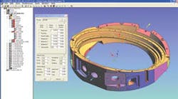
One such company is Hexagon Metrology with its PC-DMIS suite of software modules.
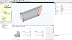
Another is Siemens PLM Software which offers stand-alone packages in addition to CMM programming capability integrated into its NX CAM software suite.
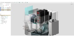
A third supplier is Delcam PLC with its PowerINSPECT software.
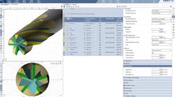
And the latest, and perhaps most interesting entry into the CMM programming market is PAS Technology and its PAS CMM package.
All of these software packages are designed to provide improvements in programming a CMM. However, trying to determine which offers the most productivity improvement potential for any given shop is more difficult than determining which CAM package is the best solution.
All of the CAM packages on the market use the Automatically Programmed Tool (APT) computer language that commonly is known as G-code. That is the reason that it is possible to use any of the packages to run any of today’s CNC machines by feeding the generated G-code through a post processor tailored to each machine to get the machine commands unique to each machine.
In CMM programming, there is no one common language similar to APT, and there are at least two languages that are incompatible with each other.
One is DMIS (Dimensional Measuring Interface Standard) and the other is CALYPSO.
Most Zeiss CMMs are equipped with controllers that use CALYPSO while CMMs made by other companies use some form of DMIS. Software developers who aim to improve CMM programmer productivity also focus on generating and using DMIS code.
A consortium of companies led by Deere & Co. was formed to try to convince all CMM manufacturers to certify that the version of DMIS that they use meets the current DMIS standard. Until that consortium is successful, there is no guarantee that any randomly chosen package could be used to generate code that will run on all of the CMMs in a shop. Even if that happens, shops that use Zeiss CMMs would have to use a DMIS-driven controller to take advantage of available software productivity tools.
In addition to language incompatibility, there is no current standard for the electronic capture and transmission of the most important information needed for inspection — the geometric dimensioning and tolerance (GDT) data that is used to describe the nominal geometry and allowable variations.
Currently, that information usually is transmitted from the designer to the manufacturer on a drawing.
There is a separate effort to develop a standard STEP file format for transmitting geometric dimensioning and tolerance data electronically. Until such a standard is established and implemented, only a few software packages are available to transmit that information electronically, and they use proprietary formulas to do it, so they are not compatible with each other.
The net result is that, in almost all cases, geometric dimensioning and tolerance data must be input manually into a CMM program.
Then there are the questions of whether a shop wants to inspect parts on its CNC machine or at its standalone CMM, and whether it wants to use a stand-alone CMM in a temperature- controlled room or, as with a portable CMM, on the shop floor where temperature variations could cause erroneous measurements.
The overarching question is, however, whether a given software package would work with all of the types of CMMs that a shop could own.
Hexagon’s PC-DMIS, Siemens’ NX suite and Delcam’s PowerINSPECT all offer a form of on-machine inspection capability. There is a growing trend for shops to use on-machine inspection as part of the machining process rather than as part of a final inspection.
The CMM software from Hexagon, Siemens and Delcam all generate reports. Because the ultimate output of any CMM operation is to report how close a part is to the design intent, the form of the report that a CMM generates and the report’s ability to effectively communicate such information is an important factor in choosing an operating software package for the machines.
But the capability of a software package to do on-machine and stand alone inspection, and to generate useful reports does not address the problem of the programming bottleneck.
All of those packages work from 3D CAD models. Siemens’ NX suite is a comprehensive CAD/CAM/CAE package that is being integrated with other Siemens Product Lifecycle Management (PLM) software to provide companies with a very extensive suite of software modules that support both the shop floor and front office.
Several years ago UGS, the developer of Unigraphics, acquired Technomatix and with it a strong CMM plugin module that was, and still is being used by other CAD/CAM packages such as Catia and PTC’s Pro/E.
When Siemens PLM acquired UGS, it changed the name of Unigraphics to NX and began an integration of its PLM software with NX. The CMM software developed by Technomatix has been integrated into NX so that the user interface for CMM programming has the same look and feel as the NX CAD and CAM modules. The NX native file format is one that allows geometric dimensioning and tolerance data to be passed electronically from the designer to the CMM programmer, and Siemens is working to automate that data into the CMM program generation process.
Delcam’s PowerINSPECT also has the user-friendly look and feel of other Delcam products. Geometric dimensioning and tolerance data is still a matter of point-and-click feature selection combined with manual data input.
Both of those packages represent some improvement in reducing CMM programming time, but the fourth package mentioned above, PAS CMM from PAS Technology, represents a quantum jump in reducing CMM programming time.
PAS CMM does not generate reports, is not a CAD or CAD/CAM package, and doesn’t drive on-machine inspection the way the other packages do. All it does is take a 3D CAD model, any 3D CAD model, and generates DMIS code that can be used by any DMIS-controlled CMM. What makes it interesting is that it reduces the time it takes to generate the DMIS code by as much as 80 percent or more.
In an actual test on a potential customer’s part, PAS CMM reduced total time to develop a DMIS CMM program for that part from the seven working days the customer had spent to develop the program to less than six hours.
PAS CMM uses a combination of sophisticated feature recognition and probe control to almost completely automate the DMIS code generation. In this example, it took two minutes to import the file into PAS CMM, two minutes to build the alignment, one minute to specify machine orientation, three minutes for feature recognition extraction preparation, 30 minutes to complete feature extraction on 880 identifiable features, and four minutes to generate the CMM DMIS code. The bulk of the time was spent in manually entering inspection parameters and dimensions (geometric dimensioning and tolerance data). That took 300 minutes. Other tests using parts from other customers had the same results.
If there was a standard format for electronically transmitting the geometric dimensioning and tolerance data, then Sam Golan, president of Pas Technology, estimates that those 300 minutes could be reduced to less than 30.
Developing that standard is a goal that several companies are working on. Golan believes it will happen, but that it will take another two years at least to realize.
Because PAS CMM is focused only on automating the generation of DMIS code from a 3D model, and because it has a very intuitive user interface, according to Golan, it takes only one or two days to become completely proficient in using it.
PAS CMM is not a direct competitor to any of the other software packages mentioned because it does not generate reports or work for on-machine probing. However, it works in conjunction with any of the mentioned packages or with software supplied by CMM OEMs to greatly reduce CMM programming bottlenecks.
