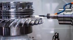


Vertical lathes (VTLs), especially large ones, are used to manufacture critical parts in most heavy industries including aerospace, wind, oil-and-gas, and many more. The bearing that supports the table and workpiece has a direct impact on the tolerance and surface finishes that a VTL can produce. This report will help readers understand how precision tapered cross-roller bearings (TXRs) used to support the VTL tables impact cut quality of the parts processed on these machines. (See Figure 1.)
VTL basics
To best explain how TXR bearings influence the performance of a VTL let’s start by providing a brief overview of the application, including a rundown of the VTL’s major components and sub-systems, along with a basic explanation of “turning,” the primary operation performed on these machines.
Figure 2 highlights the major components and sub-systems of a VTL that includes a cross slide, headstock, ram, table and CNC controls, and chip removal system see. Under the guarding and sheet metal covers there is a table drive, lube oil circulation system, tool changer, and the base-frame that supports and integrates all these components. (See Figure 2.)
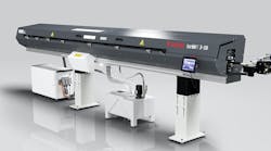
It is worth mentioning that the size of a VTL is based on the table diameter and/or the maximum size workpiece that can be turned on the machine. Typically, the VTL model number is based on the table OD in centimeters, millimeters, or inches. Examples are the Phoenix VTL 144 seen in Fig. 1, the Honor model VL-160CM VTL in Fig. 2, and the You Ji Model VTC1000ATC+C in Fig. 3.
Most VTLs have four degrees of freedom, three linear (X, Y and Z axes) and the table rotation (C axis.) The cross slide provides the “X” and “Y” motions, the ram provides the “Z” motion, and the table performs the “C” rotation. The reason these lathes are referred to as “vertical” machines are because the workpiece rotates about the vertical “C” axis when material is removed by the turning process.
Figure 4 is a typical table drivetrain that consists of a variable-speed motor connected to a gear reducer that drives the table carrier assembly via a precision rack-and-pinion gear set. Note that the bull gear is fixed to the table carrier housing that is supporting the bearing outer ring, thus rotating the bearing outer ring.
Speed capability is an important characteristic of the table bearing. Maximum table speeds range from 800 rpm on smaller machines to 50 rpm on larger machines. The limiting speeds of TXR bearings align nicely with VTL speed requirements.
Most VTL tables mount to a carrier assembly that houses the bearing, as shown in Figure 5. The table is typically slotted to accommodate jaws or chucks for clamping down the workpiece to be cut. Carriers may also incorporate pallet changers to allow entire tables to be automatically loaded and unloaded onto the machine, to reduce setup time. The type of table and maximum workpiece size determine how much weight the TXR bearing is required to support.
The carrier assembly in Figure 6 consists of the carrier (housing), post (shaft), TXR bearing, outer ring clamping plate/bull gear, preload clamping plate (spigot), preload (shim) spacers, and the table. Because the table bolts to the carrier on most VTLs, the outer ring of the bearing rotates with the carrier and the inner rings (cones) are mounted to the post (shaft), which is attached to the machine frame and stationary; this is referred to as a “dead shaft”.
Preloading of the bearing is accomplished with a shim pack that is captured between the shaft face and the preload clamping plate, as shown in Figure 6. This is referred to as a “spigot design” because it looks like a water spigot, with the “nozzle” protruding and seating on the lower inner ring (cone) backface. The shim pack also may be positioned between the lower inner ring backface and the clamping plate. The location is a matter of preference by the machine builder, either configuration is acceptable.
The thickness of the shim pack determines the preload setting. TXR bearings are preloaded to achieve the speed, stiffness, and runout requirements of this application. The outer ring clamping plate ensures that the double outer ring is securely fixed to the carrier, and it is not uncommon to the have the bull gear integrated into this plate.
Oil circulation is the most common lubricating method for VTL table bearings because it helps to maintain a lower and more uniform bearing temperature, especially at higher speeds. Closed loop circulation systems are used to filter and cool the oil to maintain the temperature around 75°F (25°C.) Oil viscosities range from ISO VG 46 to 68. It is customary to inject the oil in multiple locations around the post/shaft in between the inner rings, typically 8 to 16 injectors depending on machine size (see Figure 7.)
Turning basics
Having detailed where the TXR bearing is located in the VTL, and how it is mounted, let’s address the basics of turning – which is the primary operation of all vertical lathes.
Turning is how material is removed from the workpiece on all lathes, horizontal or vertical. What makes turning fundamentally different from milling and grinding (which removes material from a stationary workpiece with a rotating tool) is that turning removes material from a rotating workpiece with a stationary tool (insert), as shown in Figure 8.
Turning inserts are made from very hard materials (such as tungsten carbide) with the goal of cutting cleanly through the workpiece material. Both the insert and the workpiece material have a profound impact on the roughness (Ra) and visual appearance of the finished surface of turned parts, but for the scope of this report it is assumed that the insert is correct for the workpiece material.
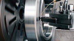
There are two turning operations that are common to all lathes: the face cut and the body cut (see Figure 8.)
A body cut turns the OD or bore of a workpiece along the Z axis. A face cut turns the top of the workpiece in the X-Y plane. The three primary turning parameters are the cut depth, surface speed, and feed rate. The cut depth is how deep the insert nose is plunged into the workpiece; the surface speed is the linear speed of the cut, or how fast the tool is moving through the workpiece; and the feed rate is how far the tool indexes for every rotation of the workpiece, and it is specified in inches/rev or mm/rev.
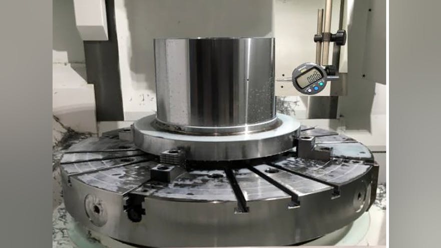
The values of these parameters are based on the material, insert, and the desired quality of the cut (rough vs finish.) The geometry of the insert and whether cutting fluid is used also factor into determining these values. The quality of the cut is judged by the runout, surface finish roughness, and visual appearance of the workpiece (see Figure 9.) Cutting parameters are not addressed here, but assume that they are properly selected for workpiece material and cut type.
Why a TXR bearing?
Before focusing on the TXR bearing, let’s review the bearing options for supporting VTL tables found in machining operations today, along with their advantages and disadvantages.
VTL table bearing options can be divided into two categories, roller element bearing and hydrostatic bearings. Hydrostatic bearings are typically used on larger tables when roller bearings of sufficient accuracy and/or load-carrying capacity are not available (see Figure 10.) Like any other bearing type, hydrostatic bearings have advantages and disadvantages.
Hydrostatic bearings accommodate larger tables than even the largest rolling element bearings available will do. They also have higher load ratings than rolling element bearings, and slightly higher accuracy.
The drawbacks for hydrostatic bearings are their cost, complexity, and speed. Hydrostatic tables are significantly more expensive, both up front and to operate, because they require a hydraulic power unit and a chiller to manage the heat generated.
Sizing and tuning hydrostatic bearings properly is very difficult, because friction power grows exponentially with speed that is limited by heat. Typically, hydrostatic bearings have speed ratings 50% less than will be possible on a table of the same size supported by a TXR bearing.
Basically there are five VTL table roller bearing configurations that have been used to support VTL tables, including the TXR bearing, thrust TRB, thrust cylindrical roller bearing (CRB), ball bearing (BB), and a cross-roller CRB (CXR.) Comparing the characteristics of each of these bearing types makes it obvious why the tapered roller XR is the most popular choice for this application (see Table 1.)
The thrust TRB design is a close second because it has comparable tilting stiffness and typically a higher load-carrying capacity. But it requires a second set-up bearing, which make the design more complicated and the overall machine cost higher. Minimizing the height of the table is one of the greatest advantages of the TXR because it makes for a less complex and more compact design than a table with a 2-TS or a thrust bearing (TTHDFL or CRB) with a TS set-up bearing (see Figure 11.)
TXR product details
A TXR is effectively double row bearing where both rows reside in the same axial location. TXR’s are referred to as “cross-roller bearings” because alternating roller’s apex is oriented in the opposite direction of its two adjacent neighboring rollers forming a cross or “X” pattern. The most common available configuration is the TXRDO and consists of a double cup (outer ring with two raceways), two inner rings, a roller set, roller separators, and roller extensions (see Figure 12.)
The rollers are designed with an L/D less than 1.0, meaning that their length is less than their diameter. This is required to achieve the 45° included angle and helps to keep the bearing section compact with large, effective rolling centers. The greatest advantage of this design is the high tilting stiffness that the effective spread yields, as illustrated in Figure 13.
Rollers have free-floating polymer separators situated between them to prevent direct contact during operation, as seen in Figure 15. Because they are free-floating and lightweight, they help to minimize the starting and running torque of the bearing. This is part of the reason that TXR bearings have the speed ratings for their size, capacity, and stiffness. The TXR bearing is “separable,” meaning the components are shipped separately and the bearing is assembled during the table installation (see Figure 14.)
The roller small ends are drilled at the centerline and a polymer insert is pressed into the hole. The insert is referred to as a “roller extension” and prevents the roller from falling away from the outer race (rib) during assembly (see Figure 15.) When the bearing is in operation, there is an air gap between roller extension and the inner race when the large end is seated properly.
TXR bearings range in size from 11 in. OD (279 mm) to 111 in. OD (2819 mm.) Sizes above 111 in. (2819 mm) are possible, up to 3.4-meter OD currently. With table ODs that are 40 to 60% larger than the bearing OD, it is possible to use a TXR bearing in a VTL with a 28-foot (8.5-meter) table.
Error motion
VTLs are used in a wide variety of industries to machine an extensive range of parts, with tolerances and surface finish requirements that vary greatly. Even parts with lower precision requirements still need a table bearing with precision-class tolerance. Unfortunately, the bearing features controlled in the ABMA
19.2 or ISO 492 do not meet all the requirements for this application. (See Selecting TRBs for Machine Tools: Understanding Tolerance Standards, Part 1.)
Because of the unique requirements of this application, the VTL table bearing manufacturer is compelled to control internal geometry to minimize the assembled bearing error motion, not the runout. (See Selecting TRBs for Machine Tools: Going Beyond Tolerance Standards, Part 2.)
Runout is the displacement of the surface of a rotating object (see Figure 16), while error motion is the displacement of the axis of rotation (Figure 17.) Although error motion is what matters most in this application, assembled bearing runout is the traditional method of validating whether all the component tolerances are met when the bearing comes together. Error motion is typically much less than the bearing runout.
The error motion of the VTL table bearing contributes directly to the runout and surface finish of the workpiece. It manifests as a table tilting error, a characteristic that directly impacts workpiece runout and face flatness (see Figure 18.) The tilt amplitude is the bearing error multiplied by the height of the cut/measurement above the bearing centerline. Tilt error is minimized with TXR bearings because the roller and raceway geometry are controlled beyond ISO and ABMA standards. It is important to remember that the altitude of the cut test does have an impact on the results.
It is important to understand that when measuring the tilt error motion of the table there are two components to the error motion: 1) the synchronous (repeatable) and the 2) asynchronous (non- repeatable), as shown in Figure 19. The synchronous tilt error motion contributes mostly to the runout of the workpiece where the asynchronous is primarily responsible for the surface roughness. The visual appearance of the surface finish is a function of frequency/modulation of the tilt error motion.
The bearing is one of many components on a VTL that must work nearly flawlessly to performance requirements. It is important to note that although the bearing is one of the primary contributors to the runout, surface finish, and visual appearance of the workpiece there are other factors, outside the bearing, that also can impact the quality of the cut. The rigidity and natural frequency of the ram, headstock, cross slide and base need to be taken into consideration as well. The workpiece material inserts and cutting parameter along with the workpiece material also impacts the quality. Finally, any external vibrations that can be transmitted to the table post such as motors, pumps, compressors, gear drives, etc. will also show up in the table error motion signal.
Summary
The advantages of the TXR bearing over other bearings of similar design and other bearing configurations are why it has become the standard for VTL table bearings. Their compactness and small cross-section provide a simplified table design together with a maximum running accuracy. Their wide, effective spread ensures high stability and maximum rigidity. Low starting and running torque reduce heat generation to yield good speed capability.
The list of the characteristics that make TXR bearings very attractive for VTL table bearings includes:
- Stiffness: 45° half included cup (outer raceway) angle and preload yields a high moment/overturning stiffness.
- Speed: On-apex construction assures true rolling motion.
- Capacity: TRB design yields high radial and axial capacity.
- Accuracy: Internal tolerances and features yield very low error motion.
- Compact design: Two rows in the space of one simplify the post/shaft, carrier/housing, and lubrication system design.
Although there are other options for VTL table bearings, the TXR is by far the most popular and common for these reasons. It ranks highest in almost every category, as shown in Table 1. With ongoing efforts to continually improve its performance, it will most likely remain the leading choice for bearings to support tables in VTL applications for years to come.
Eric Faust is an Application Engineering Specialist with The Timken Company. Contact him at [email protected], or via LinkedIn.