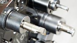
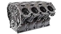
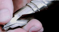
For many shops, the addition of new metalcutting technology is all about buying machine tools, with cutting tools, toolholding, and workholding dealt with as afterthoughts. But such a strategy seriously undermines the productivity of new processes. Instead, shops should examine the benefits of machine, tooling, and workholding together before plunking down large capital investments.
Cutting Tools
Cutting tool selection hinges on operation type.
- Walter's X-Tec F4042 tackles shoulder milling
- Iscar's Heliturn is for turning;
- Valentines ValGroove is a parting-and-grooving system
- Valentine's Valmill 350 cutters handle slotting/slitting;
- Komet's Duplon drill makes holemaking easy; and
- Emuge's coolant-fed thread mill optimizes the thread cutting process
Cutting tools run the gamut from high-speed steel to carbide to ceramics to polycrystalline diamond. But with thousands of cutting tools to choose from, how does a manufacturer decide what to use? The consensus among tooling suppliers is to start by working with tooling specialists that have the expertise to make major productivity improvements through the proper application of tooling.
Ideally, say these suppliers, shops should approach tooling specialists even before they purchase machines. According to Michael Abberley, president of Sandvik Coromant Co., "Consulting with a tooling specialist allows a shop to implement an expert's insight into the decision process when considering the purchase of a new machine. After evaluating the need to be filled by the new equipment, a tooling specialist may suggest tooling options that would allow the void to be filled with an alternative machine that better maximizes the full capability of the tooling. In some instances, the increased need might be met solely through the implementation of newer and more appropriate tooling. At a minimum, the specialist will be able to maximize productivity by identifying the most appropriate tooling to be used with the new machine."
Where many shops go wrong, agree tooling companies, is basing tool selection on initial cost, rather than looking at their impact on the cost of machining operations. Overall, the cost of tooling is typically 3% to 4% of the cost of producing a part. But tools can positively or negatively influence other production costs in regard to coolant, setup, and labor.
Generally, the right tooling has an immediate impact on production costs. For instance, wear-resistant tools extend tool life, thereby lowering tooling costs and reducing toolchange times. Tough tools that run at high speeds and feeds significantly improve cycle times and lower per-piece costs. And accurate tools that minimize tolerance deviations and provide consistent part finishes often reduce or eliminate scrap.
Defining requirements
The process of tool selection involves a number of steps, says Jim Strolberg, vice president of technology with Walter Waukesha Inc. These all relate to the application:
- Define the operation. Identify whether it's a roughing, finishing, or one-cut operation. Also, does the operation call for through-spindle coolant, minimal-quality lubrication, or dry machining? All of these will impact tooling choice.
- Define part geometry. It's important to identify challenging features for instance, if the part calls for 90 angles or shoulders.
- Define workpiece material. Today's demanding applications take shops beyond machining cast iron and steel to a variety of materials: magnesium, aluminum, HSLA steels, and composites. And just as materials have become more sophisticated, so has tooling. In fact, cutting tool companies are introducing new tools optimized for specific materials practically every day, says Tom Benjamin, director of marketing at Valenite Inc.
- Determine workholding rigidity. End users should consider factors such as whether or not parts have thin walls or demand the use of tools with long overhang. Both of these conditions can lead to vibration and require rigid workholding to compensate.
- Define operation type. This may seem like an easy step. After all, shops know if they're doing milling; turning; parting/grooving; slotting, slitting, or cutoff; holemaking; or tapping/threading. But a lot more is involved, comments Valenite's Benjamin.
For milling, the cost per cubic inch determines productivity. Therefore, it's important to understand how much material a tool removes, how quickly it comes off, and the cost per tool. It's also a good idea to examine the design of cutter bodies and check that inserts are securely held in pockets.
In addition, says Dennis McNamara, product manager Milling at Seco-Carboloy, achieving better productivity in milling is often a matter of getting back to basics in terms of maintaining the average chip thickness that is prescribed for a cutting insert's specific edge preparation and operating tools within the optimum torque/power zone for an individual machine. To be most effective, shops should match the correct diameter of cutter to their machines' power bands. Again, tooling specialists can help in this process.
In turning, tool performance relates to cost/piece. So look at effective cost per edge per insert and how quickly metal is removed. Generally, tooling selection is a matter of selecting the optimum insert based on substrate and top-form geometries.
For parting and grooving, Valenite suggests tool engineers keep their options open because of the variety of applications that call for grooving, parting, turning, undercut grooving, profiling, and internal and face grooving. Normally, differentiating factors include the use of single and double-edge inserts, chipbreaker geometries, carbide grades including PCD and CBN, and facegrooving options.
With slotting, slitting, and cutoff tools, cutters should provide excellent chip evacuation at high feedrates. Therefore, look for a close-pitch design with all inserts positioned in-line. Then check if the inserts have strong edge geometries capable of tackling hardened materials with little vibration. It's also helpful to partner with a tooling supplier that offers a variety of coated and uncoated grades for roughing and finishing in steel, stainless steel, cast iron, and aluminum.
Effective holemaking takes cost/hole into account. And rigidity is crucial. According to Jerry Hanna, manager of holemaking products at Kennametal Inc., rigidity goes beyond the tool itself to the machine tool, spindle, spindle connection, and workholding. "When there are problems in drilling, shops are quick to blame the tools," he remarks. "But the problem is often with the machine or the setup fixturing, in particular. You should provide extra support for weak portions of a workpiece, especially when drilling multiple holes in a part."
Hanna says end users should also consider:
- Drill length to hole diameter. Is the hole depth 2x or 10x diameter? To optimize the tool rigidity, use the shortest drill possible for the hole depth required. This is especially important for difficult-tomachine workpiece materials.
- Hole tolerance. This is important when deciding among solidcarbide, modular, or indexable-insert drills. For instance, high-performance, solid-carbide drills typically deliver tighter tolerances than indexable-insert ones. However, if tolerances can be opened up, shops may base decisions on the economics or convenience of modular or indexable-insert drills instead.
- Application. How the tool will be used influences tooling selection. Shops drilling stacked plates, for instance, should use solid-carbide tools, says Hanna. However, indexable drills are preferable if a drill enters on an angled surface greater than 5.
- Coolant flow. Coolant should flow at the proper volume and pressure. Deep-hole applications require through-tool delivery. With short holes (2D), though, this type of delivery is often unnecessary and uneconomical.
As with holemaking, cost/part is the most important aspect of tapping/threading. For example, while thread-rolling tools may appear to be expensive up-front, they can drive down the cost/part in the long run, reports LMT-Fette.
Thread-milling tools give users other options, explains Mark Hatch, product manager at Emuge Corp. He says shops using these tools should buy machining centers with CNCs providing 3-axis helical interpolation, throughspindle coolant (250-psi minimum), and spindle speeds of 5,000 rpm or higher. With these features, shops can exploit advanced thread-milling technology like multifunctional tools that drill, chamfer, and thread in one operation.
Tool selection
Once the operation is defined, it's time to select tooling. Again, tooling suppliers can help further the process by explaining how a tool design/geometry, substrate material/composition, and coating relate to cutting performance. They can also help with issues such as whether to use a positive or negative geometry based on workpiece material, the best geometry for interrupted cuts, what kind of toolholding is necessary, and how many teeth are needed for milling and drilling operations. And they can supply optimum speeds and feeds for a given operation and tool.
Tooling specialists also keep up on the latest and greatest cutting tools. Considering the number of tools introduced each year, keeping apprised on all the new tools can be an overwhelming job for shops, but here's a snapshot of some innovations to ask about:
Milling
- Micrograin-carbide substrates, which combine higher compressive strength and hardness than traditional carbide grades.
- New cutter-body designs that securely hold inserts in the pocket. Cutting tool companies say that eliminating insert movement increases d.o.c. and feedrates.
- Advanced coatings such as PVD-applied multilayer TiAlN/TiN, nickel coatings, and AlCrN. Many of these coatings provide hot hardness, oxidation resistance, and longer tool life. In some cases, they may have metal-removal benefits in high-speed cutting, dry or minimum-quantity lubrication (MQL) machining, and hard machining (50 to 70 Rc).
- New tools that tackle multiple operations.
Turning
- Deformation-resistant cutting inserts that withstand the heat generated when turning titanium and nickel-based superalloys.
- Inserts that combine special coatings with cobalt-enriched-zone substrates for hard interiors and tough surfaces. These inserts are well suited to dry and MQL operations.
- Grades that provide extra toughness to reduce premature cutting-tool failures in steel-turning applications.
- Optimized cast iron tool grades offering heat and abrasion resistance for machining compacted graphite iron and other difficult cast irons.
- Inserts with helical curves on their top-face rakes. Reportedly, this ensures good chip control even on problem materials.
Holemaking
- Twist drills for small bores.
- Adjustable fine-boring tools with replaceable-insert holders.
- Multiple-flute reamers with changeable heads.
- Microadjustable boring heads with electronic measuring.
- Extra-long drills for 30xD (without a peck cycle).
Toolholders
|
CERAMIC TOOLS Advancements in ceramic technology have greatly broadened the applications for these tools, which are best suited to highspeed machining of cast iron, hardened steels, and heat-resistant alloys. But these inserts can be tricky to use, says Dale Hill, applications engineer with Greenleaf Corp., so it's best to work with a tooling specialist to pick the appropriate tool for a given application and machine tool. With ceramics, rigidity is a key concern. Inserts must be held securely in the pocket, and special attention should be paid to the rigidity of the machine tool, toolholding, and fixturing. Otherwise, shops will end up with premature tool failure rather than higher cutting speeds. Ceramics come in two general categories: silicon-nitride based and aluminum-oxide based. Hill says the first category is good for cast irons and ductile irons. As for aluminumoxidebased ceramics, shops have a choice between aluminum oxide with TiC for hardened steels and aluminum oxide with embedded SiC whiskers. The whisker-reinforced ceramics have superior strength compared to other ceramics, making them a good choice for heat-resistant alloys. They also handle milling jobs which is often not the case with other ceramics. A recent innovation in whiskerreinforced ceramics is the use of coatings that extend tool life. According to Hill, these tools are best applied in medium to light-duty jobs, such as continuous turning (semifinishing and finishing). |
Lyndex-Nikken recommends using toolholders that consistently maintain a G 2.5 rating at the rated spindle speed.
More shops are leaning toward shrinkfit toolholders (such as these from T.M. Smith) because of their rigidity and gripping force.
Toolholding is the key to achieving the speed and accuracy possible with today's advanced machines and cutting tools. Unfortunately, many manufacturers make a critical mistake by using old toolholders in new machine spindles. This practice not only degrades the performance of the new machine, but it also results in improper fit of new toolholders that companies may later purchase, says Jack Burley, vice president of Engineering at BIG/Kaiser Precision Tooling Inc.
He suggests manufacturers factor the cost of critical tooling accessories into the entire equipment package. Otherwise, what they "saved" by re-using old tooling will be lost through inefficient utilization of their machines and cutting tools.
Shops ready to buy new toolholders should keep four critical aspects in mind:
- Rigidity. This is achieved by taper contact. If a toolholder doesn't fit properly into the spindle, a machine can't achieve its full performance potential. The experts at Lyndex-Nikken Inc. recommend using toolholders supplying at least 80% taper contact.
- Accuracy. This is determined by the amount of runout allowed. The general consensus is that maximum runout be 0.0002 in. TIR at 4 D to maximize cutter performance. It's a good idea to look for shank tolerances of ANSI standard AT-3 or better for spindle-taper accuracy.
- Balance. Imbalance creates vibration and chatter, which negatively influence metal-removal rates, tool life, and surface finishes. Therefore, closely examine the quality of toolholders using set screws or collets both of which can create unbalance at high spindle speeds. And, according to Lyndex-Nikken, use toolholders that consistently maintain a G 2.5 rating at the rated spindle speed.
- Gripping power. This is the holding power of the toolholder. If using collets, ensure they allow positive gripping as close to the work as practical. In addition, reports Briney Tooling Systems, it's wise to choose multipurpose, high-precision collets with a wide clamping range (1-mm collapse).
HSK and shrinkfit holders
The proliferation of HSK and shrinkfit toolholders are perhaps the two major trends of the past five years. For many, HSK has become the preferred shank because of the inherent rigidity and accuracy. Many machining centers, particularly those from Europe and Asia are built with HSK spindles as standard. But beware of shoddy workmanship, cautions Valenite's Benjamin. He says HSK holders should meet required tolerances when a spindle is running at 40,000 rpm.
As for shrinkfit toolholders, manufacturers particularly in the automotive sector are employing them in high-speed, highvolume work. Currently, the major drawback to this technology is its initial cost, but this is expected to drop in coming years. And the production benefits are compelling.
With a shrinkfit tool, reports Briney, users achieve rigidity as close as possible to an integralshank tool but at less cost and with greater flexibility. On average, shrinkfit holders impose 10,000 lb of gripping force on a tool shank, exceeding the gripping capability of collet, milling, and hydraulic chucks. The tool shank is also gripped 360 the entire length of the bore.
Some things to keep in mind when purchasing shrinkfit tooling, according to experts at Techniks Inc.:
- Buy from a supplier licensed from the original patent holder. This ensures the product is manufactured to a certain standard.
- Look for high holding power and extreme rigidity both necessary for precise machining.
- Demand TIR of 0.0002 in. or better.
- Ensure the toolholder is factory balanced to 15,000 rpm or better, particularly if using in high-speed applications.
- Is the taper ground to AT-3 or better?
Toolholding types
According to Greg Pratte, vice president of marketing and sales for Centaur Precision Tools, shops want toolholders that "centralize" round-shank tools. Otherwise, they may end up with off-center conditions that adversely affect productivity.
Pratte says three types of toolholders centralize cutting tools:
- Precision collet chucks clamp to an accuracy of 0.0005-in. TIR on the cutting tool about an inch from the face of the collet chuck. These versatile toolholders accommodate drills, mills, reamers, and taps and cover a range of tool diameters.
- Precision milling chucks with straight-sleeve collets offer greater gripping strength and accuracy than collet chucks. Their accuracy is 0.0004 in. on the cutting tool up to 4 in. from the face of the milling chuck.
- High-precision chucks grip the full diameter of a cutting tool without collets. There are different styles including hydraulic, mechanical, and shrinkfit that provide clamping accuracy less than 0.0001-in. TIR on the cutting tool 4 in. from the chuck face.
Techniks supplies a quick checklist of what to look for in different types of toolholders. In all cases, it recommends that toolholder tapers are ground to AT-3 or better:
Collet chucks
- Coated nuts for maximum holding power on the tool shank.
- Precision-ground collets 0.0004-in. TIR or better.
- Precision balanced with lab report documenting TIR, balance, and taper specs.
Drill chucks
- High holding power.
- Low TIR 0.0008 in.
- Balanced for high speed.
- One-piece design for higher rigidity.
End-mill holder
- Bore manufactured to H5 spec or better.
- Balanced to 10,000 rpm.
Hydraulic holder
- High holding power and rigid design.
- Spiral grooves in bore.
- Low TIR 0.0001 in.
- Balanced for high speed.
- Sleeves to fit different-sized shanks.
- Leak-proof design.
Milling chuck
- Roller-bearing chuck mechanism.
- Collets to fit different-sized shanks.
- 0.0002-in. TIR or better.
- Balanced for high-speed operations.
Workholding
Workholding devices grip and locate parts for operations such as turning, milling, drilling, and grinding.
- Swing clamps from Carr Lane Roemheld;
- Hardinge workholding collets;
- an expanding collet from Rovi;
- Schunk's Unilock quick-change palletizing system;
- a hydraulic-operated fixture from Royal Workholding; and
- SMW Autoblock's EM-A clamping mandrel.
Workholding manufacturers offer a variety of devices that grip and locate parts for turning, milling, drilling, grinding, and other types of machining. Overall, however, as production changes, calling for smaller lots in a just-in-time environment, end users are demanding turnkey solutions that deliver quicker part changes, tighter tolerances, and more versatile and durable part holding. For this, they have the option of custom-designed equipment or off-the-shelf devices, reports Richard C. Spooner, chairman of the Workholding Product Group of AMTThe Association For Manufacturing Technology and president of Powerhold Inc.
With the proper workholding, shops can improve efficiency about 10%, according to the experts at NorthTech Workholding/Kitagawa. And when this improvement is applied over thousands of parts, the result can be a huge cost savings.
The company recommends that end users consider five factors when buying workholding:
- Workpiece dimensions
- Workpiece material
- Production volume
- Shop conditions
- Accuracy and tolerances required
These factors will all point the way to what type of workholding is needed. In addition, says Bernie McAloon, sales manager at Royal Machine & Tool Corp., Berlin, Conn., shops may also want to think about the number of parts a fixture accommodates, the ease of load/ unload for operators, and production requirements such as the best way to hold parts for machining and the number of operations involved.
Holding turned parts
Shops holding parts for turning have a variety of options from which to choose. For instance, they may opt for 3- or 4-jaw chucks, which grip parts for safe machining and establish workpiece location and orientation with a degree of specified repeatability.
With these kinds of workholding devices, the shape of the workpiece determines the number of jaws needed. But the array of workpiece shapes makes it difficult to reduce the selection process to simple rules of thumb. That's why NorthTech/ Kitagawa recommends exploiting the experience of workholding engineers.
One trend gaining momentum is the use of sealed chucks that are impervious to the entry of dirt, chips, and fluid. The obvious benefits to these chucks relate to savings in labor, grease, and downtime (currently needed to lubricate workholding). In addition, says Sid Roth, president of SMW Autoblok Corp., sealed chucks lubricate all internal parts with each cycle of the jaws opening and closing. This keeps the gripping force constant, improving part accuracy.
Shops can also use diaphragm chucks, which provide the benefits of repeatability and consistency of clamping force. These chucks rely completely on the diaphragm for opening and closing the jaws. Since there are no sliding parts, repeatability is directly related to the consistent elastic deformation of the diaphragm.
Roth says that most diaphragm chucks are self-contained and frontactuated, using a pneumatic cylinder for opening the chuck and releasing the workpiece. He recommends using this type of chuck over a self-contained version, which doesn't let users increase gripping force when necessary.
Another method of holding turned parts involves the use of collet chucks. According to Daniel P. Soroka, workholding engineer at Hardinge Inc., collets are a small, but powerful tool that incorporate the following features:
- The capability to accurately grip a workpiece, resisting both rotational forces and multidirectional cutting loads.
- The capability to amplify actuation force, converting it into gripping force.
- The inherent ability to rapidly release a workpiece.
- The ability to operate at high repetition levels without loss of accuracy-or material failure.
- The ability to operate over a range of rotational speeds with minimal loss of gripping force.
- The ability to accomplish all these with a minimum of rotational inertia.
A common misconception about collets is that they're limited to gripping round, square, or hex-shaped materials. In reality, they secure nearly any shape or part form that fits within the collet's envelope.
Hardinge reports that gripping force is crucial when using collets. Hence, it helps to understand some of the factors that affect gripping force:
- The level of axially applied force. Typically, the higher this is, the higher the gripping forces.
- The collet-closing angle (or head angle), which is generally determined by the machine tool builder and the collet manufacturer.
- The friction of the workpiece with the gripping surface of the collet. Lower friction reduces gripping forces. Workholding manufacturers compensate with features such as serrations or carbide impregnation of the gripping surfaces to overcome slippage or pushback.
- The friction of the collet-closing angle with the spindle. The sensitivity of this effect can result in lost gripping force and accelerated wear of the collet and its receptacle.
- Full bearing of the collet to the workpiece, which is necessary for high gripping force. This is maintained when the collet order hole is properly fitted. If the order hole is too large, only the outer face of the collet grips the workpiece and a geometric mismatch occurs around the circumference, resulting in low gripping force. Too small a hole results in only the inner-head angle making contact, which creates high gripping force and concentricity problems.
Ronald L. Posen, president of Rovi Products Inc., suggests end users demand the following in their expanding collets:
- Is the collet system dead length? It is crucial that an expanding collet system hold true length for linear dimensions.
- How well does it hold concentricity? Repeatable concentricity is a must when using any type of collet, whether it is for holding on the O.D. or the I.D.
- Is it versatile? Some collet systems only work with one particular style of collet, while others are more adaptable and work on several styles of collet systems with slight modifications.
- How easy is it to set up? The easier it is, the quicker the setup will take, thus increasing the overall profit margin of the job.
- Does the supplier/manufacturer have sufficient inventory? Once a collet system has been implemented, nothing is worse than finding out that replacement parts are not in stock.
Clamping mandrels advance automated part handling
As the metalworking industry further automates, there is increasing need for precision workholding to clamp parts on their interior surfaces. This workholding must be rigid enough to hold the part accurately against the cutting forces applied and accurate enough to produce high-quality parts. The ideal device for this process, says SMW Autoblok's Roth, is the expanding mandrel.
The advantages offered by mandrels for I.D. clamping are numerous with concentricity and rigidity the most important. The mandrel operates by drawing a thin-wall clamping sleeve over a taper in the mandrel body and expanding the sleeve. The sleeve is manufactured from special steel and carefully ground for accuracy. Actuation is either manual (by turning a bolt) or powered by hydraulics and a drawbar.
Mandrels come in seven types:
- Single-taper cone.This type of mandrel is the standard EM-A or EM-B and actuates either manually or by a drawbar. Single-taper cone offers the flexibility of varying lengths and diameters.
- Tailstock actuated, which mounts on a lathe spindle and relies on the tailstock pressure for actuation.
- Mounted into the Morse taper of a tailstock. This type of mandrel, which normally supports the workpiece held by the lathe headstock, is typically powered by quill actuation.
- Mounted between centers. These mandrels rely on pressure from both headstock and tailstock centers for actuation. This type can be a single or double-taper and grip a workpiece in more than one location.
- Expanding-jaw-type mandrels use small jaws that expand out from the mandrel body to grip the workpiece. This is generally used on machined bores or with special work pieces such as pistons.
- Flex-ring-type mandrels use expanding rings to grip thin-wall parts without distortion.
- Hydraulic (membrane) type, in which hydraulic pressure deforms a membrane, causing it to expand against the I.D. wall of the workpiece. This type of mandrel is dedicated to one size only and does not have the flexibility to work on more than one diameter.
Vises and clamping systems
Like choosing other workholding devices, vise selection depends on production requirements. Vise size and configuration are best determined by workpiece shape and the machine tool to be used. Cycle-time length also plays a role in the selection process. If, for example, the cycle time is short, a shop may opt for a power-operated vise to reduce clamping-cycle time.
According to Kurt Mfg. Co., shops should look for strong, rigid vises that provide vibration-dampening qualities. For a high level of process flexibility, they may want to consider modular vises with multiple clamping stations or tombstone setups. In addition, mounting vises to tablemounted foundation plates or indexing units generally makes the most of the workholding envelope.
In some cases, custom-engineered workholding may be the best choice when setups are designed around specific parts where complex processes, high throughput, and high quality are required. These setups maximize machining-center output using high-density designs and fast load/unload features. In general, however, advises Kurt, vises are good for single-part or low-quantity production, and multiple-vise setups and custom-engineered solutions are better suited to high-volume jobs.
When it comes to clamping systems, comments Derek Evans, manager, application engineering, Carr Lane Roemheld Mfg. Co., shops should turn to fixture/system designers that can help them select clamping, supporting, and positioning elements for hydraulic workholding systems. For example, a workholding expert can help pick seals in each clamping element that are compatible with the machining center's hydraulic fluid.
Evans says that if clamping elements have to withstand high-pressure or flood coolant or be subject to a predetermined short clamp/ unclamp cycle time (as in robotic load/unload applications) then double-acting clamping components should be used. That's because double-acting elements are completely sealed, preventing the ingestion of external fluids. They also unclamp faster than single-acting elements do.
Reducing setups through palletization
Shops can slash production time by palletizing their parts. In fact, manufacturers such as Erowa Technology Inc. and Schunk Inc. report palletizing systems reduce part setups by allowing operators to fixture parts off machines. These systems also speed transfers between machine tools.
Skip Thompson, Erowa's president, suggests shops ensure they are working with suppliers that have product ranges encompassing pallets, automation, and software-integration tools.
He adds that shops shouldn't be misled by the common assumption that automation is only for production environments. "By palletizing your workholding systems, you are providing a common interface to your machine and robot, regardless of workpiece configuration and size. Today's jobshop and low-lotsizemanufacturing environments can profit more by simple workpiece automation than any production environment." Palletization also allows shops to run machines unattended, providing additional production benefits.
Some things to keep in mind when looking at pallet systems:
- Standardization. The system should have common components holding the blank and common fixtures to secure it to the machine tool.
- Accuracy. The design should guarantee consistent placement of the workpiece.
- Modularity. The chuck/receiver should accommodate a selection of pallet configurations.
Rotary tables and accessories
Shops purchasing rotary tables should evaluate issues including long-term reliability, high-production capabilities, maintenance, accuracy, and flexibility.
Rotary tables can be interfaced to machine tools as additional axes or installed with independent controls. If choosing the latter, it's a good idea to get a control that receives commands through an RS-232 port for ease of programming and safety.
According to Lyndex-Nikken, rotary tables should be constructed to minimize wear on bearings, gears, worm screws, and worm wheels. If the table does not maintain longterm rigidity, shops could end up with excessive downtime for maintenance and out-of-tolerance workpieces. Rotary tables should also be sized properly to maximize machine potential but not so large they interfere with toolchangers and machine-axis movement.
|
AM MANUFACTURING: TOOLING AND WORKHOLDING CHOICES AM Mfg. Co. is examining tooling and workholding as part of its equipment-evaluation process for its round and octagonal workpieces. It has determined that any decision to buy vertical machining centers, lathes, or mill-turn machines will take into account and into budget cutting tools, toolholders, and workholding equipment. The company is currently predisposed toward advanced coated-carbide cutting tools to minimize tolerance deviations and provide consistent part finishes. Wear resistance will also be a priority, but not at the sake of missing opportunities to improve overall cycle times. Currently, the company is working with tooling specialists to determine how different tools impact cost/piece in turning operations and cost/in. 3 for milling. These costs not the initial price of the tools themselves will be among the criteria used to judge new tools. As for toolholders, the company has a great deal of experience with conventional collet chucks, but it is intrigued by the opportunities afforded by shrinkfit toolholders. The company is consulting with its machine tool suppliers as well as a number of toolholding vendors in an effort to pick the best toolholding based on its applications (and eventual selection of machine tool). In the end, the company may use customengineered workholding, but its major concern involves quick changeovers of small lots. In addition, whatever system it selects must be flexible and hold parts accurately. The company is also leaning toward performing setups off-machine to free up valuable cycle time. The company is seriously considering lathes or mill-turn machines, so it is investigating the pros and cons of using collets versus jaw chucks. Again, the decision rests on what workholding will best optimize the company's processes based on its eventual machine selection. |
ACKNOWLEDGMENTS
AMERICAN MACHINIST would like to thank the following for their contributions to this article:
ATS Workholding, Anaheim, Calif.
Balzers Tool Coating Inc., Amherst, N.Y.
BIG/Kaiser Precision Tooling Inc., Elk Grove Village, Ill.
Briney Tooling Systems, Bad Axe, Mich.
Carr Lane Roemheld Mfg. Co., Ellisville, Mo.
Centaur Precision Tools, Miami, Fla.
Ceratizit USA, Warren, Mich.
Chick Workholding Solutions Inc., Warrendale, Pa.
Emuge Corp., Northborough, Mass.
Erowa Technology Inc., Arlington Heights, Ill.
Greenleaf Corp., Saegertown, Pa.
Guhring Inc., Brookfield, Wis.
Hardinge Inc., Elmira, N.Y.
Ingersoll Cutting Tools, Rockford, Ill.
Iscar Metals Inc., Arlington, Tex.
Kennametal Inc., Latrobe, Pa.
Komet of America Inc., Schaumburg, Ill.
Kurt Mfg. Co., Minneapolis
LMT-Fette, Cleveland
Lyndex-Nikken Inc., Mundelein, Ill.
NorthTech Workholding/Kitagawa, Schaumburg, Ill.
OSG Tap & Die, Glendale Heights, Ill.
Powerhold Inc., Middlefield, Conn.
Rego Fix Tool Corp., Indianapolis
Rimeco Products Inc., Willoughby
Rovi Products Inc., Simi Valley, Calif.
Royal Machine & Tool Corp., Berlin, Conn.
Sandvik Coromant Co., Fair Lawn, N.J.
Schunk Inc., Morrisville, N.C.
Seco-Carboloy, Warren, Mich.
SMW Autoblok Corp., Wheeling, Ill.
Stellram USA, LaVergne, Tenn.
Sumitomo Electric Carbide Inc., Mt. Prospect, Ill.
T.M. Smith Tool International Corp., Mt. Clemens, Mich.
Techniks Inc., Indianapolis
Tool-Flo Manufacturing Inc., Houston
Valenite Inc., Madison Heights, Mich.
Walter Waukesha Inc., Waukesha, Wis.
Workholding Product Group of AMTThe Association For Manufacturing Technology, McLean, Va.
