CGTech, the developer of NC/CNC simulation programs, is shipping the latest version of its VERICUT CNC machine simulation and optimization software. VERICUT 7.1 brings significant time-saving enhancements for manufacturing engineers developing, analyzing, inspecting, and documenting CNC programming and machining processes. While many of the features were originated by CGTech developers, it emphasized that hundreds of the program’s enhancements were “customer driven.”
California-based CGTech specializes in numerical control (NC/CNC) simulation, verification, optimization and analysis software technology for manufacturing, and its VERICUT ® software product is widely used to simulate CNC machining, to detect errors, potential collisions, or areas of inefficiency.
VERICUT lets machine shops to eliminate the task of proving-out NC programs manually, reducing scrap loss and rework, and it optimizes NC programs in order to save time and improve the surface finish on parts. The program is compatible for simulating all types of CNC machine tools, including those from leading manufacturers, but it also runs as a standalone program and can be integrated with leading CAM systems, such as Catia V5, NX, Creo (Pro/E), MasterCAM, EdgeCAM, and GibbsCAM.
“VERICUT 7.1 builds on CGTech’s highly successful VERICUT 7.0 release, and subsequent point releases, that contained over 700 customer requests delivered throughout 2010,” stated product marketing manager Bill Hasenjaeger. “Version 7.1 contains over 400 customer requests and further improvements to VERICUT’s user interaction, simulation capabilities & analysis, cutting tool creation, and CAD/CAM integration.”
The Project Tree introduced in VERICUT 6.0 has been refined again in the new release, to make project sessions simpler to launch. A shortcut Toolbar has been added to enable quick transitions to a particular Project Tree branch. Holding the cursor over the icons will display what branch the icon goes to. Model file names are shown in parentheses for all models that have model files associated with them. Double clicking on NC Programs, or NC Subroutines, displays the appropriate file selection window. Also, NC Programs and NC Subroutine files can be added by simply right-clicking in the Project Tree. To quickly correct any possible user errors, a general purpose Undo/Redo button is available at the top of the Project Tree.
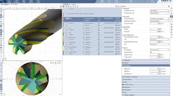
Cutting conditions are shown in the status display and are available when stepping through the program using NC Program Review. The feature shows detailed information about the cutter’s engagement with material, including: axial depth, radial width, volume removal rate, chip thickness, maximum surface speed and contact area.
Tool Manager
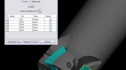
To simplify creating a VERICUT tool library, CAD solid models of inserts and holders can be imported into VERICUT. This new feature added to the Tool Manager displays the CAD Geometry window that allows easy identification of which parts of the CAD model file correspond with holders, cutters, or inserts. CATIA v5 and STEP models are supported.
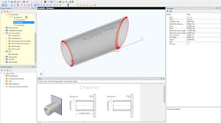
It is possible now to create and display coordinate systems in the Tool Manager, and these coordinate systems can be used to align tool components.
CAD Model Assembly
A new feature, Assembly, in the Open model file selection window lets the programmer extract all individual components of a CAD assembly file and store them in their own model definitions. If Assembly is toggled “on” (checked) a separate model will be created for each component in the CAD model. When toggled “off” (unchecked) all components are used to create a single model. This feature supports STEP, CATIA v5, and NX model types.
The VERICUT Reviewer incorporates all the functionality of NC Review mode in a stand-alone viewer that does not use a license. The Reviewer can play forward and backward while removing and replacing material. Error messages and NC program text is highlighted when a collision on the stock or fixture is selected. A tool path line display is optional. The user can rotate, pan and zoom just like normal VERICUT, and the cut stock can be measured using all the standard X-caliper tools. The “Reviewer” file can be saved at any point in a VERICUT session.
With the new VERICUT report enhancements, users can preview and customize report templates to include features such as pictures in tables, links to files, and links to websites. These reports have become increasingly valuable for VERICUT users to share CNC machining process information throughout their organization and supply chain.
Machine simulation
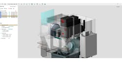
A new feature has been added for VERICUT collision checking: it is possible to stop the simulation at an “exact” collision point between the machine components. This new feature is turned on/off using the new Stop At Collision check box on the Start/Stop panel. The new logic is applied only to the Machine Simulation collision checking, and only to machine components other than the stock component. It is not applied to the holder/stock and tool/fixture collision checks. While simulating a NC block with the Stop At Collision box checked, VERICUT will stop in mid-motion at each collision point. Clicking the Step button continues simulation to the next collision point (or to the end of the motion if no other collisions exist).
