Generate NC Tool Paths with Microsoft Excel
By Greg Nuspel
Many parts require you to do repetitive calculations to create a tool path. If you’re programming manually, that can be a daunting and time consuming task with a large potential to make errors.
Many shops opt to use a CAM system or parametric programs, but not every machine or shop has these capabilities.
With Microsoft Excel, you can set up arrays to complete the calculations, and with a few tricks, you can use that program to produce the actual lines of code. This process also is useful when your machine is capable of parametric programming, but the processor is too slow to create a smooth tool movement.
Typical problems that can be solved are large radius concave or convex surfaces, torus sections, angular faces, large chamfers, spirals, and more. All of these items can be described mathematically, and that is the secret of using Microsoft Excel. At times like this, you’ll wish you had stayed awake in trigonometry class.
An example is cutting a large curved surface.
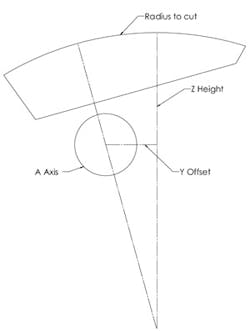
The radius of the main surface is 24 in. If you don’t have a lathe with a 24-in. swing, this becomes a difficult part to machine, never mind the large fixture it would take to hold the 8-in. by 14-in. by 3-in. piece of material. Setting this up on a fourth axis fixture makes machining the part practical.
Any point tangent to the surface can be calculated, and a Y, Z, A position for the machine can be determined.
First, calculate where the center of the arc of the part is in relation to the A axis.
Then, calculate where the tangent point is.
If you moved the A axis in tenths of a degree (above), imagine how many errors could be produced if you manually calculated that and entered the values into your program.
Using Excel, you can create an array (see the Excel Tips sidebar that accompanies this) that will do all this for you.
First, you need a series of numbers to represent the angles of the A axis.
To determine the angle of rotation required to complete the arc, use trigonometry:
SIN(a)=5/24, a=12.02, SIN(b)=9/24, b=22.02
Round the answer to 12.1 and 22.1, respectively.
For troubleshooting purposes, it is best to break your calculations into individual steps.
This is where Excel is a great tool. Each column can become one step of the calculation, and that gives you an easy way to see errors.
Remember: Excel works in radian, not degrees. Therefore, you will have to use the RADIANS formula command to convert to radians and the DEGREE command to convert back to degrees.
The Y position is calculated as follows:
Sine of the angle X 18 (distance for center of A axis to arc center) Y=SIN(RADIANS (A$2:A$344))*18
The Z position is calculated by:
24(radius) minus the cosine of the angle times 18
Z=24-COS(RADIANS (A$2:A$344))*18.
The data presented has too many decimal places for use in a controller. To set the number of decimals, use the formula command =FIXED(x. xxxxx,4,true) the number 4 sets the decimal positions to 4 (true makes Excel drop commas for large numbers).
You may think that you have to take all this raw data and enter it into your program manually because it is in a format that your machine cannot understand.
However, there is a simple solution that will give you all the code so that it can be cut and pasted into your the formulas so that you can use the method of selecting arrays explained in the sidebar. If you use the pop-up dialog box, you will have to select the arrays by dragging your mouse from top to bottom.
If you want to make a more complex series of moves, you always can add a line separator in the final formula.
That way, when you load it onto your machine, it will create multiple lines of code.
For example, when doing a torus, you may want to move out to the new radius then feed down before you cut around the part.
If you are using a Haas machine, the formula will look like this:
=CONCATENATE(“G01 X”,I$2:I$50,”; Z”,J$2:J$50,”; G03 I”,-1*I$2:I$50).
The line created by Excel looks like this:
G01 X10.25;Z-.25;G03 I-10.25.
When the formula is loaded into the controller, you will get:
G01 X10.25 Z-.25
G03 I-10.25
The array produces the repetitive series of three moves in one line, but your controller sees it as separate lines.
If you experiment with Excel, you will find that it provides an excellent tool for taking care of repetitive calculations and eliminating transposition errors.
It enables you to run macro/ parametric equivalent programs that require a large amount of calculations on machines with slow processors more quickly.
So practice your trig and you will find that you are only limited by your imagination. By using Excel as shown in the sidebar, you’ll be able to get your machine to run a wide range of moves.
Greg Nuspel is a journeyman machinist working for Cheema Tool and Manufacturing in Calgary, Alberta, Canada.
Greg has been machining for 15 years with 8 years of CNC programming experience.
His specialty is creating parametric programs and solving the complex tool paths for his shop. He created this method while trying to get a smooth tool path on one of his shop’s older Haas mills.
