Applying Insights, Resources for Smarter CNC Programming
Although CAD/CAM software is used for almost all CNC machine programming these days, it helps immensely if the programmer also understands G-code — the common term for the most widely used numerical control (NC) programming language.
This is the second of two entries in which the author reports on available resources and references that help machine shops improve productivity and the bottom-line performance.
In my time as an application engineer, I was involved in a large project that required a team of us (all application engineers) to come up with a process for transferring an production program from a line of manual machines to new CNC machines. Because the part was manufacturerd in many sizes, a short lead-time from one type to another was imperative. So, all the programming was done from scratch, and had to be proven as quickly as possible (like, what isn’t?) to get the machines running and maintain output levels.
Fortunately, I was working with some pretty smart and accomplished guys. All of us could read G-code fluently, which helped considerably with the proving-out process. Any minor revisions to feeds, speeds, or toolpath changes could be made right at the machine using a simple CAD/CAM program called Inplot to verify the new path.
Inplot runs directly from G-code, which allows an accurate display of the equipment’s motion. (It can be downloaded from the web at www.I-Logic.com.) Once the part path was proven we would edit the changes into the CAM file while the equipment was cranking out parts.
The machines were set up to process multiple pallets in sequence, and an operator was required to run three or four of these at a time. To lessen the operators’ work load a number of macros were used: To check for alignment in case of an operator misload; to check certain crucial dimensions and adjust cutter compensation accordingly; tracking tool wear, part count, etc. This allowed the operator enough time to perform the other tasks needed to maintain production levels.
Then, a video was made of the production process. I viewed it on my computer along with the G-code. Minor changes were made to the G-code, saving about 3% of the cycle time (1.5 min) for all types of the part that were being made. This is a production program, and thus a machining process, that will run for years, so a minute-and-a-half per cycle adds up pretty quickly. Again, understanding the G-code made a difference to our effort.
Because probing can add some more time savings, some of the CAD/CAM developers are providing posts that accommodate probing output. This makes it much easier for the CNC programmers to add these routines as macros to the CNC machine.
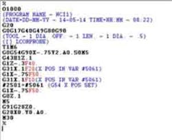
I have created what I refer to as a "repost" for such a task. During the toolpath programming using the CAM system, the programmer adds a comment line, such as ([ ] LCORPROBE). This informs the repost that what follows is a probing routine to find the X edges of the workpiece, and then resets the G54 X datum accordingly. The toolpath that was created as a milling path now is converted to a probing path with the associated code to set G54 X zero. Illustrated here is an example of the sequence.
Example 1.

Example 2.

Example 3.
Example 4.
Example 5.
Example 6.
Example 7.

Example 1 shows the G-code generated for a milling operation. Example 2 shows the path that this code generated.
As you can see, it is just a mill to the edge, then rapid in Z. The code is reposted with the probing path in place of the milling path. Example 3 shows the modified reposted output.
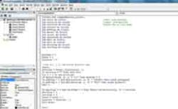
Note that the code has changed; it will take two separate readings, first for reference and then to store the position in the proper work offset. Then, the probe retracts and rapids to Z home. This is something I created using the Visual Basic that’s embedded in MS Excel. Example 4 shows some of the code used.
Around the shop I have found many uses for VB in Excel. One of my favorites I called "SUB": It’s a utility that saves time when proving-out a program
that will be used later to create multiple parts per cycle. I know that many CAM developers have multiple-part tool strategies, but having done a lot of programming and set-up myself I found it much easier simply to program one part in the CAM system. After this is proved-out on one piece then the program gets reposted through SUB, which then outputs the multiple part code.
This saves time. Rather then interrupting the cycle at prove-out and trying to jump around tool to
tool,I run only one part. If it checks out, and the program proves-out, I load the repost and have only to be concerned that my work offsets are correct — which I will know after running the first tool. From that point, I no longer need to monitor the process.
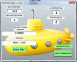
Example 5 shows the front end of SUB macro.
I simply enter parts per cycle as well as stations I need to rotate the code. This is done when using double vises where the rear position usually has the X stop used for both, which means that the rear vise is locating the part on the wrong side unless the part is turned 180 degrees.
Generally, if this is a first operation from oversize stock
this doesn’t really matter, but if it’s a subsequent operation where the datums now have been created, it could cause problems.
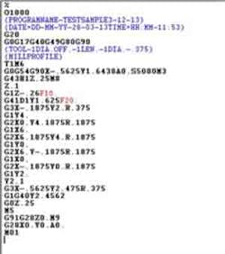
Example 6 shows the proven code and Example 7 shows the code for running the job on two double vises on a subsequent operation.
In example 6 you see the posted output for tool 1, and in Example 7 you see the reposted format.
Because all the repost does is apply the original
G-code from the proven file and transpose it into a multiple part file, there is no reason to fear a loss in translation. As you can see, two separate subroutines have been created by the post. The O1 is used where the part is positioned with the stop on the left, and O199 is used for the position where the stop is on the opposite side and the code is rotated 180 degrees.
All this is all done internally, and all the user needs to do is fill in the parameters. The average person could learn its use in less than five minutes. Then, using Inplot or any system that reads toolpaths, it’s possible to verify the new output.
I hope this article has caused readers to think about using technology to its fullest potential advantages.
Arvin Cook has been active in precision manufacturing for over 40 years, including work as an application engineer for a large machine-tool sales organization, and a contract tool maker for the Scientific Instrumentation Shop of Harvard University’s School of Engineering and Applied Sciences.
Contact him at [email protected]
About the Author
Arvin Cook
Contact him at [email protected]